|
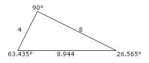
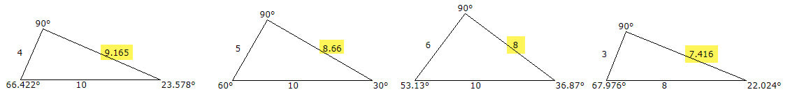
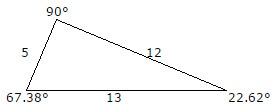
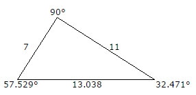
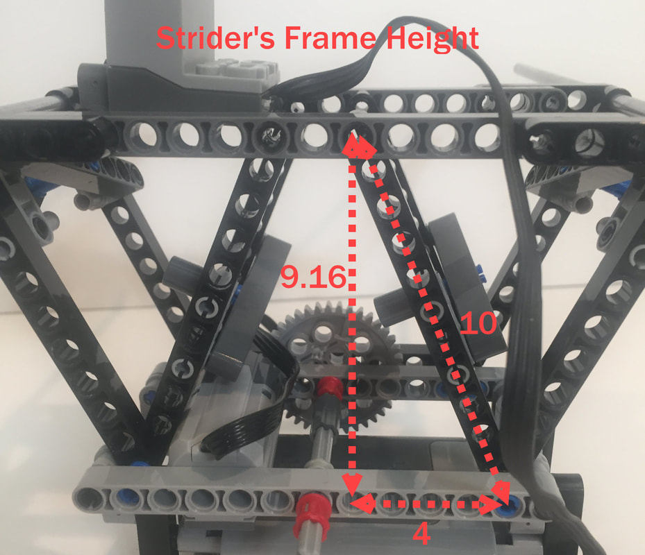
I rushed my Klann Ver 2 build and didn't build the outer frames in an optimal way: 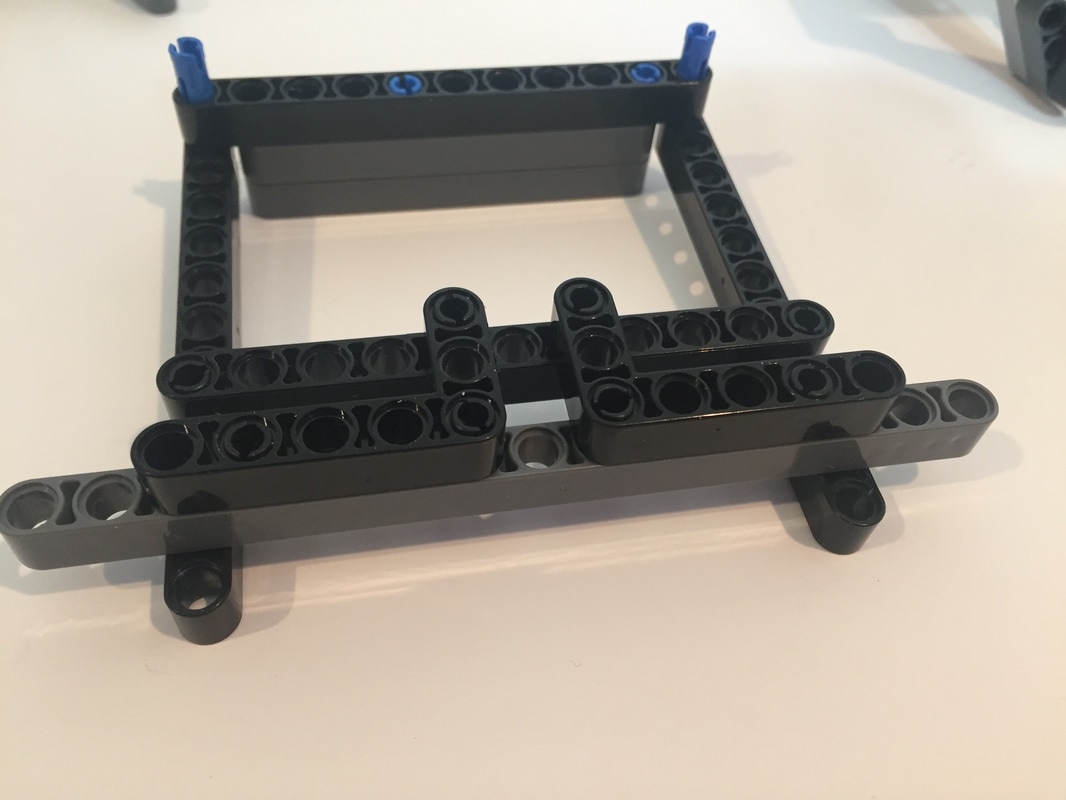 The only thing keeping this frame's corners at right angles are the two 3x5 L-shaped LEGO parts. If this frame were put under a lot of force, like would happen at a larger scale, the corners would be subjected to torque that could easily cause the rectangle to collapse. To avoid this diagonals need to be added, which will convert the rectangles into triangles and lock the corner's angles. The challenge with walkers in LEGO is we often need diagonals for rectangles that define the linkage's parameters. In other words, these diagonals often need to be the hypotenuses of right triangles. As you can see below, my Klann's upper support rods are 7 holes above the motor's axle, and the lower support rods are 2 holes below the motor's axle. Neither of these lengths work with a 3-4-5 or 6-8-10 right triangle with LEGO parts for hypotenuses. What can we do using the integer lengths of LEGO's beams? 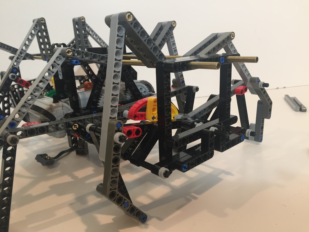 NOTE: When determining the length of LEGO beams the first hole is always counted as 0! If you don't measure LEGO beam lengths in this way you won't be able to use the Pythagorean theorem to calculate which beams to use as hypotenuses. Fortunately, with LEGO we don't have to be at precise integer numbers, and we can use hypotenuses that are "close enough". 1. Hypotenuses for rectangles of height 7. Plugging in a 90 degree angle with a side length of 7, plus a few other whole number sides into the Pythagorean theorem yields this near integer number triangle: 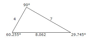 I used this triangle for Klann's inner frame where two 9 hole beams create hypotenuses of length 8:  I also used this.triangle for TrotBot's frame: 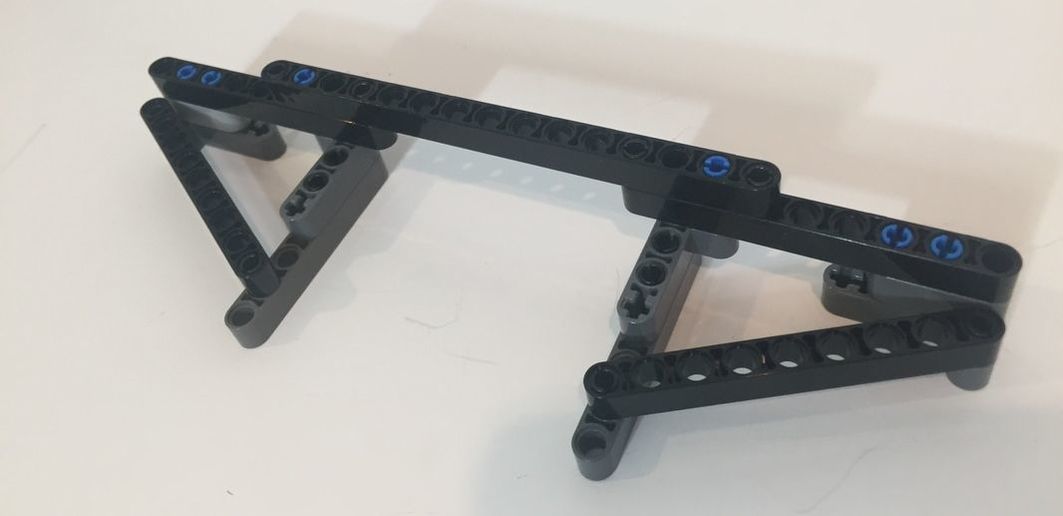 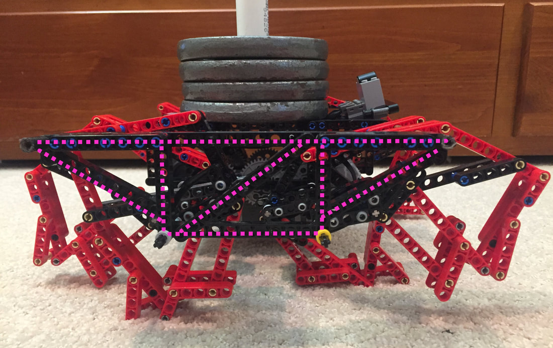 Triangles convert bending forces to tension and compression, which even plastic LEGO parts can handle well  Strider's Outer Frame's Triangle 2. Hypotenuses for rectangles of height 9. We can also connect the top and bottom beams of Klann's frame with a hypotenuse: 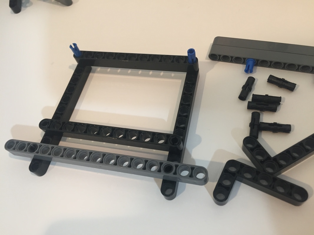 Plugging a 90 degree angle with a side length of 9, plus a few other whole number sides into the Pythagorean theorem yields another near integer number triangle: 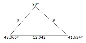 So, 13 hole LEGO beams can be used to lock Klann's outer frames into triangles, like this: 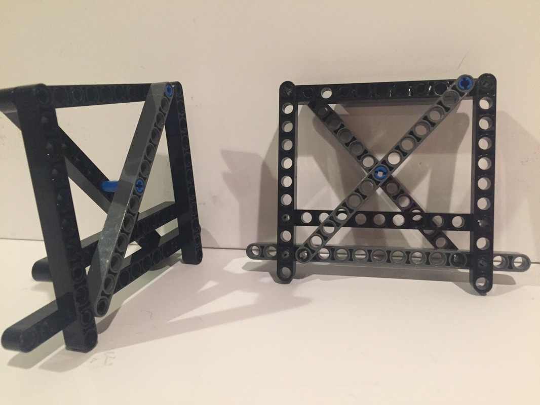 Here are a few other useful triangles for LEGO frames:
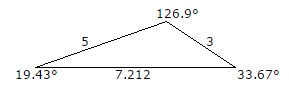
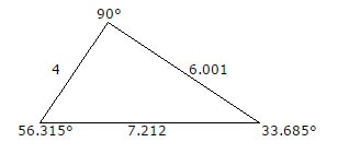
 Also, the below 5-3 bent beam can be used as a hypotenuse. 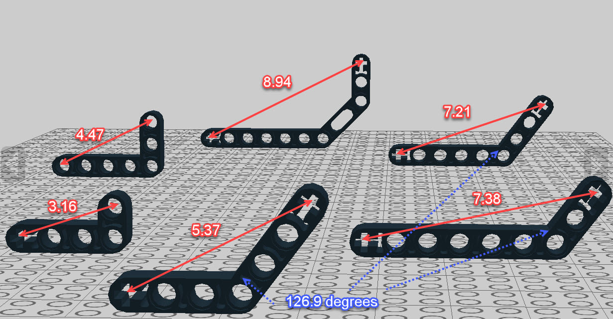
You can create more triangles by lengthening a side of the above parts by attaching a LEGO beam to it.
 LEGO beam lengths for creating frames of varying heights
6 Comments
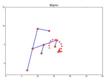
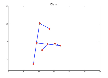
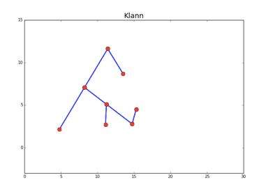
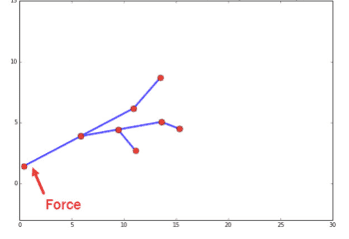
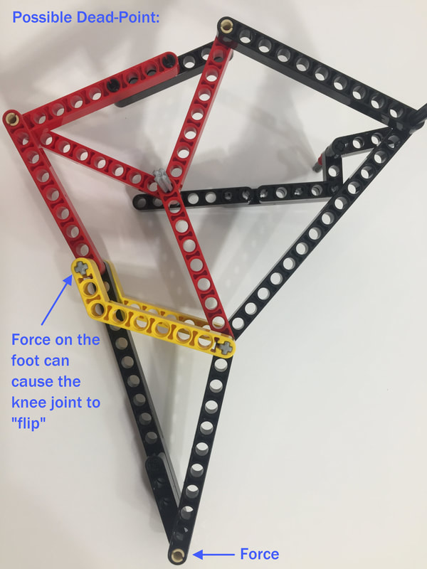
When two linked bars are nearly parallel their connecting joint can easily flip orientations and cause the linkage to lock. This phenomena is known as a "Dead Point", "Toggle Point", or "Singularity". Here's an example of what our Klann Ver 1 experienced, since it used a configuration of the linkage where the "knee" joint came close to being straight :
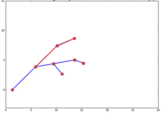
The below right picture is near the Dead Point, where two bars highlighted in red are nearly parallel:
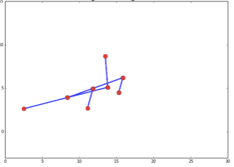
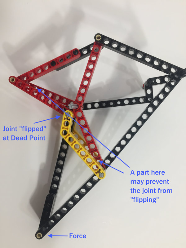
Due to the force on the foot, the joint can hyper-extend and "flip" as shown below, which causes the linkage to lock and can destroy gears and parts:
Similar to how animal joint hyper-extension is prevented by structures like ligaments and elbow bones, linkage joint hyper-extension can be prevented by adding structure. 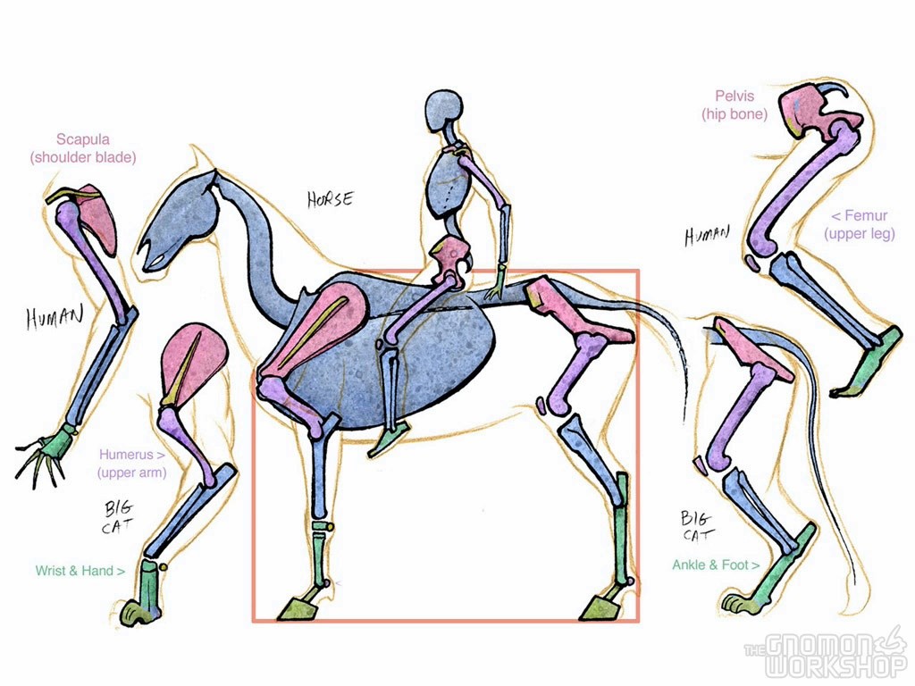
Animal Joint Hyper-Extension is Prevented by Structures Like Ligaments and Elbow Bones. Credit: Marshall Vandruff. Click the image to access his Introduction to Animal Anatomy
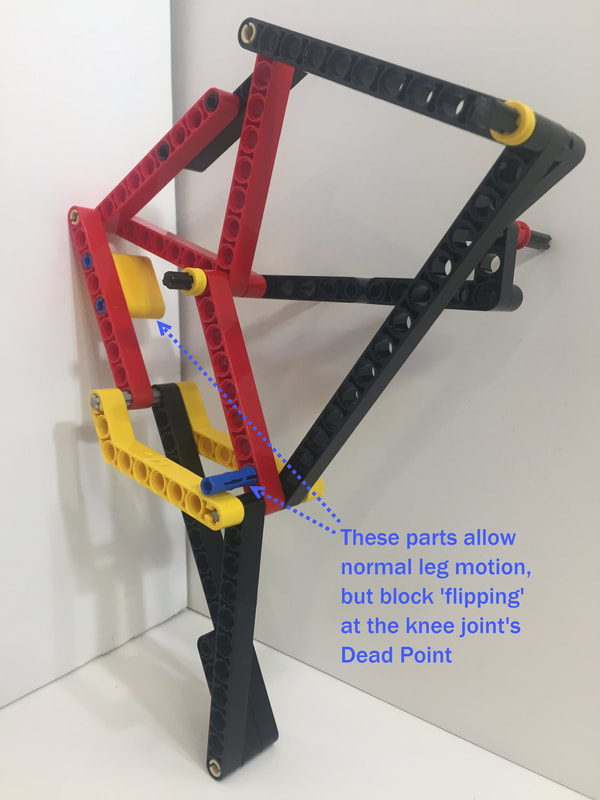
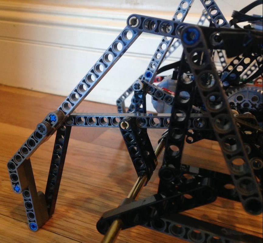
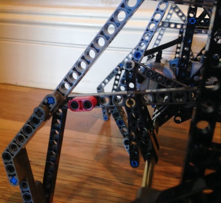
Side Comment: did you notice how the knees of mammalian quadrupeds' rear legs don't actually bend backward? As can be seen by the green foot bones and blue shin bones, the backward bending "knee" joints of horses and cats are actually their ankle joints, and their lower legs aren't their shins but are instead long feet, and so they walk on the "balls" of their rear feet with their heels far off the ground. No wonder us humans are more agile when we aren't "caught flat footed" and are instead on our toes ready for action. Below are some examples of joint "hyper-extension blockers" in LEGO. The following solution for Klann Ver 1 blocked the joint from flipping with the addition of a 2-hole red LEGO beam:
Dead-Points are also know as "change points", which all Parallelogram linkages have: As shown below, Strandbeest has (nearly) a parallelogram linkage in the center of the mechanism, and its knee joint can also flip:
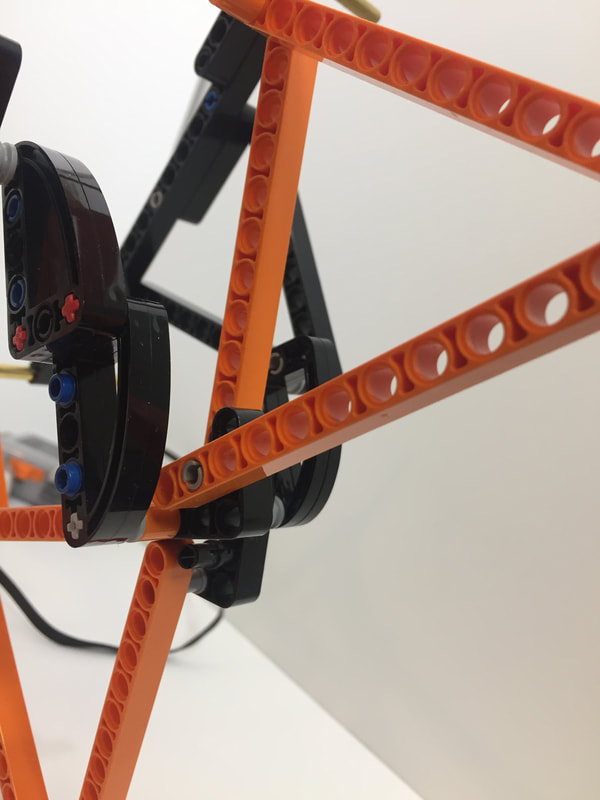
Strider's knee joint also has a potential dead point. As you can see below, Strider's Ver 2's knee joint hyper-extends inward during the weight-bearing phase of the crank's rotation, but the more important angle to consider is between the Rocker and the Coupler bars. While 136 degrees is much less than 180 degrees, if enough weight is added to the robot then the crank's joint can be pushed up and to the right, increasing the angle to 180 degrees and causing the knee joint to flip and then lock (see further down). 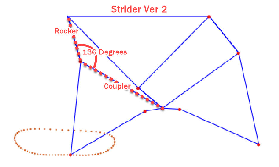
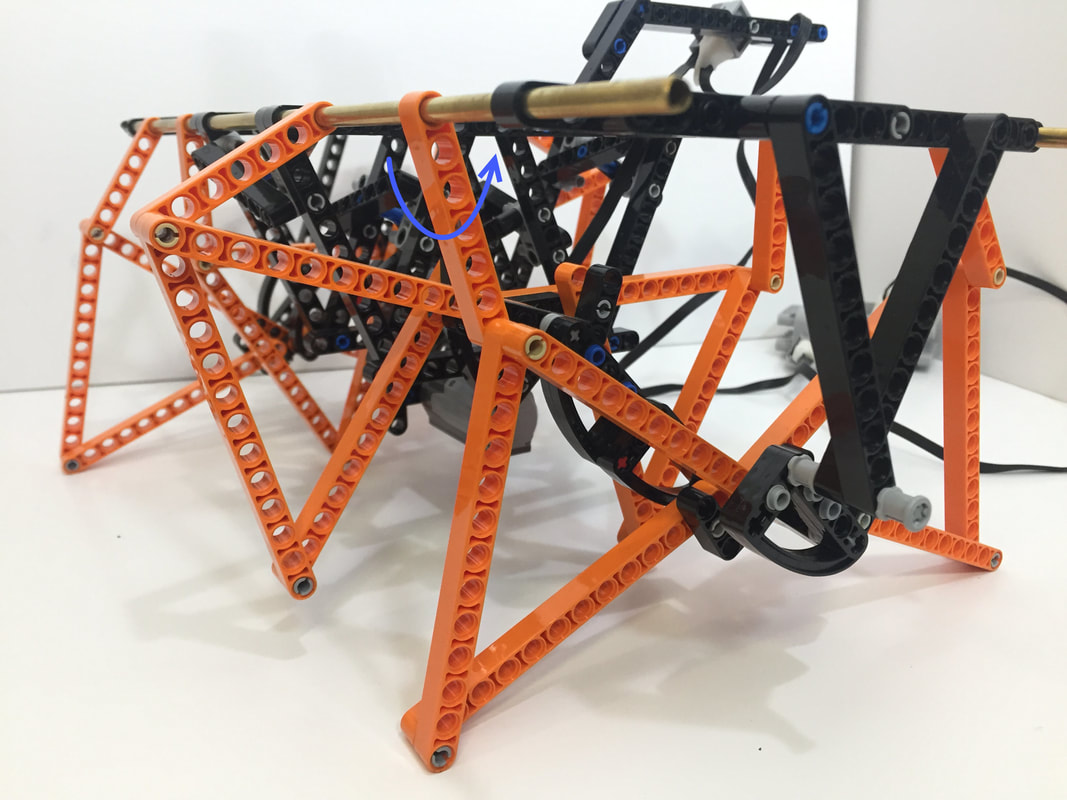
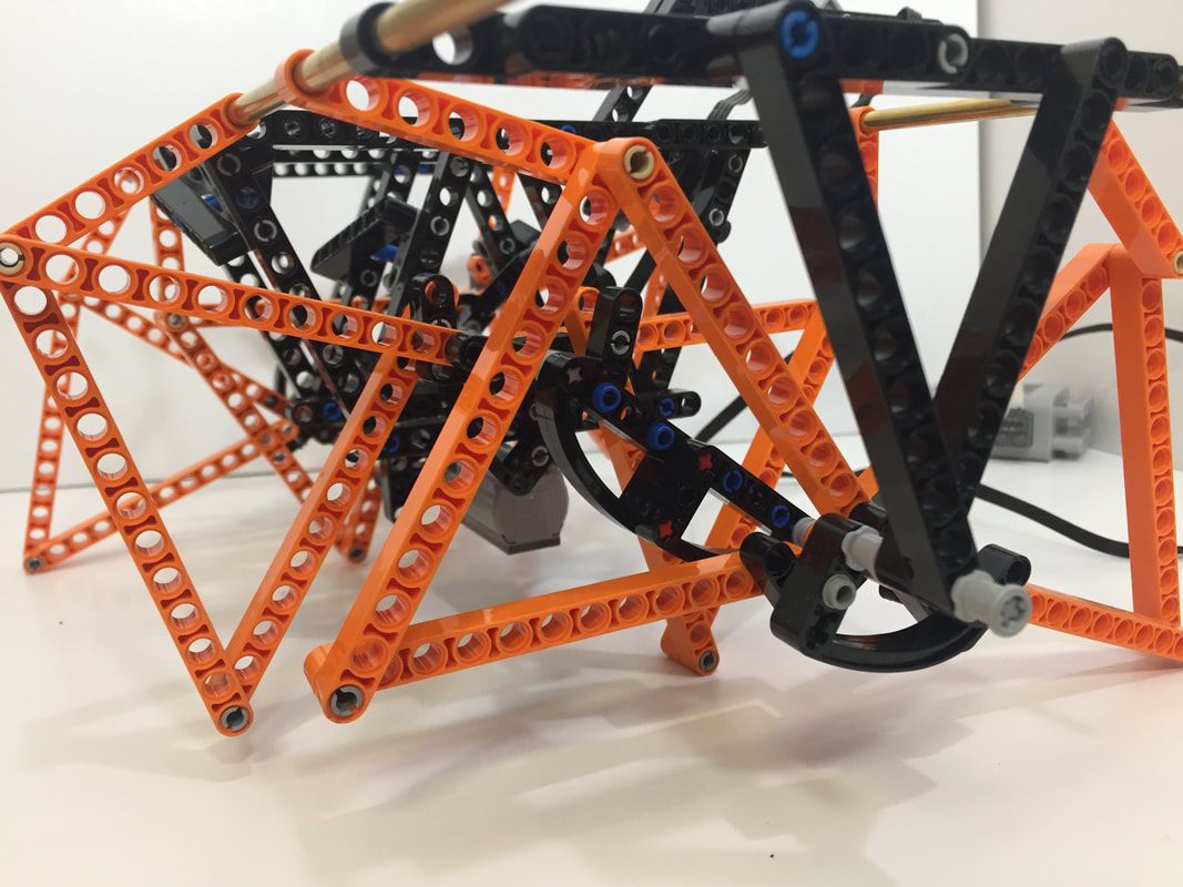
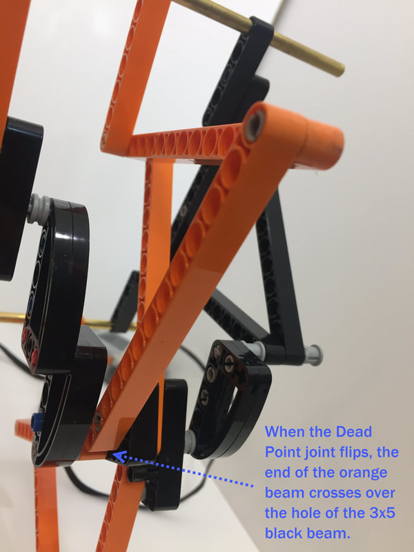
Strider with its Knee Joint "Flipped" at the Dead Point
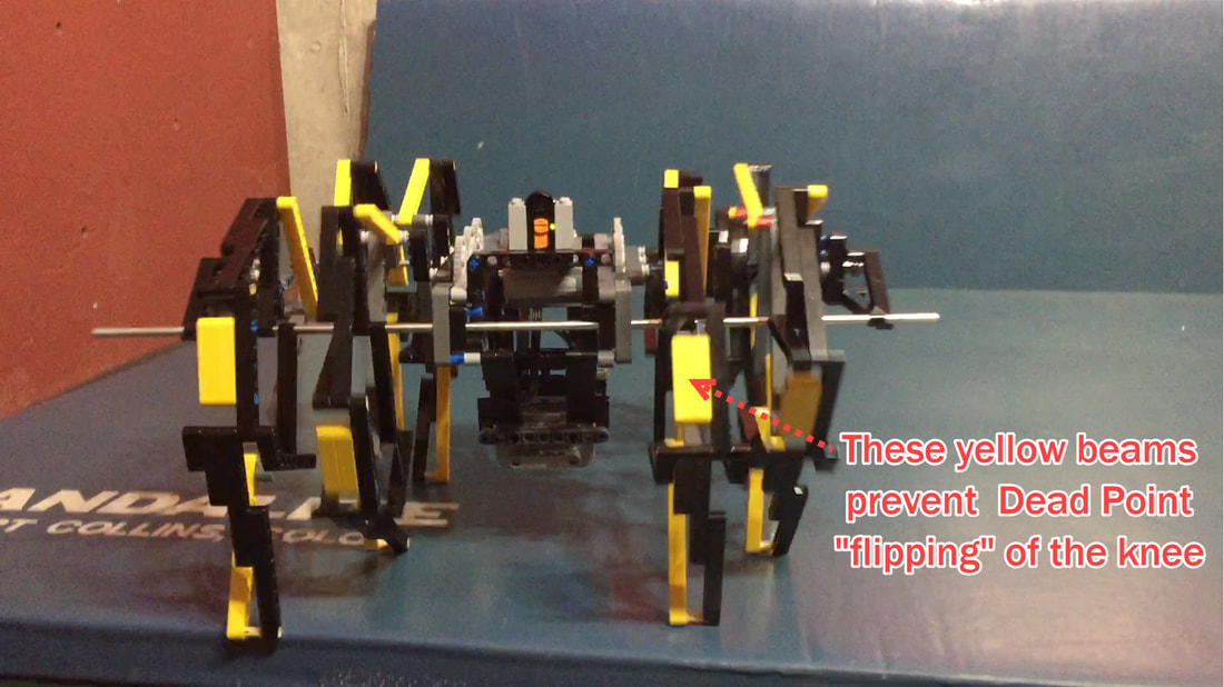
Below shows how we prevent knee joint flipping, viewed from the bottom of the robot:
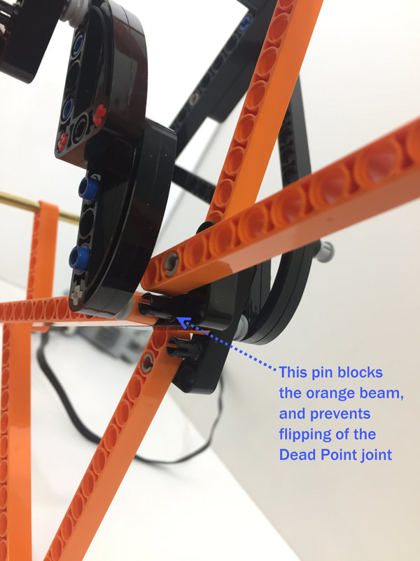
Strider Ver 3's angle between the Rocker and Coupler is smaller than Ver 2's, and therefore its knee joint has less of a tendency to flip: 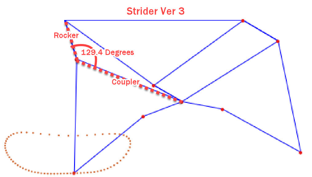
However, adding enough weight to the robot could still cause the joint flip. Therefore, Strider Ver 3 uses blue LEGO pins to limit knee hyper-extension: 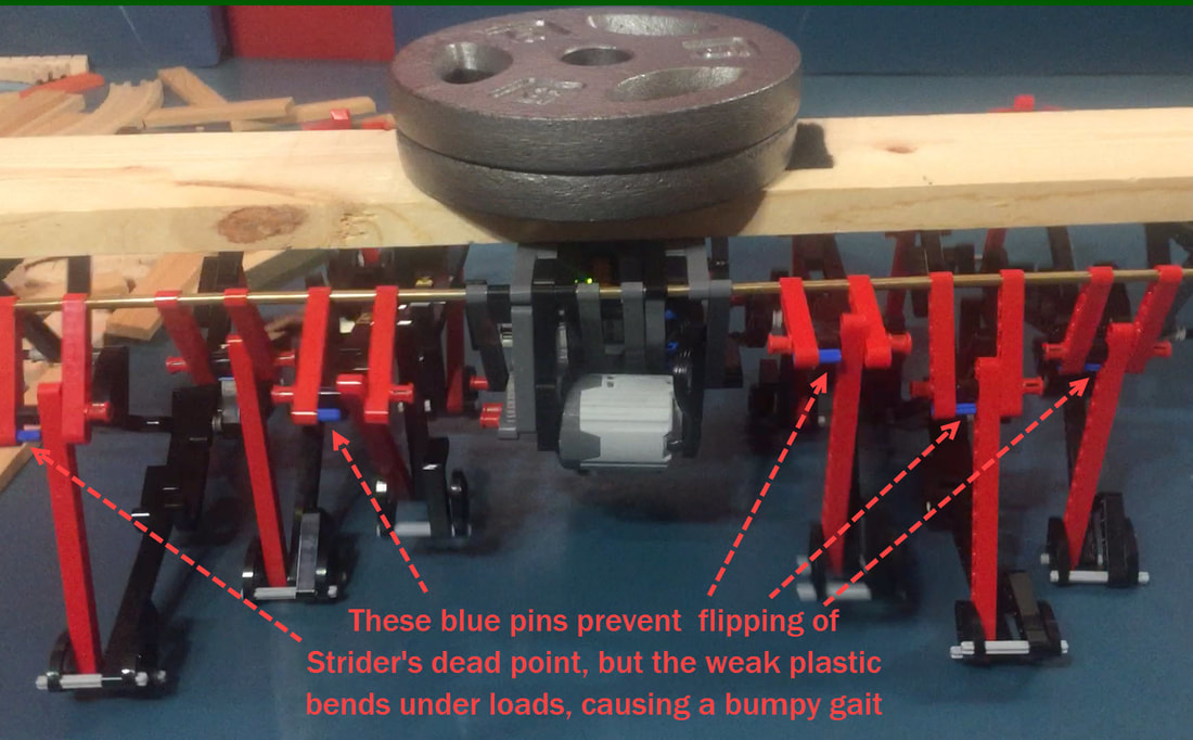
In the following experiment we added stronger "hyper-extension blockers" to a Strider robot using Linkage Variation #6, which we tested with a 25 pound load. The blue pins were still used, but an additional part was added to the front of the knee that presses against the shin if the knee hyper-extends too far. 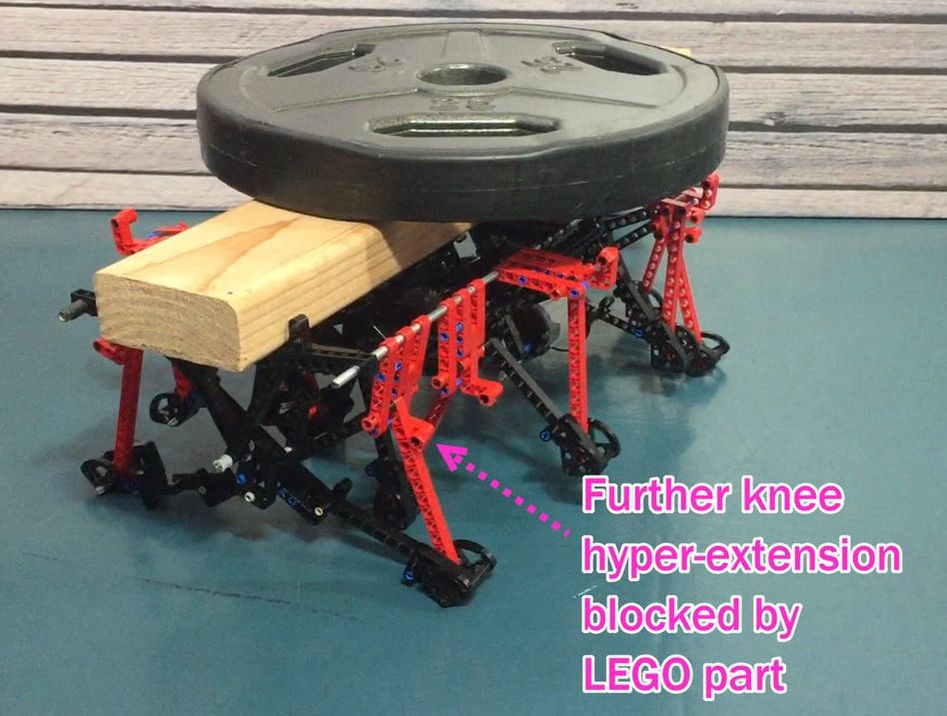
Below is a video of the test. Notice when the weight is initially placed onto Strider, the inner knee on the right side hyper-extends slightly, but not enough to prevent Strider from lumbering away under the 25 pound load:
Note: before performing this test, the plastic LEGO axles were replaced with steel axles to handle the torque. Other than that, and the 2 steel support rods, all of the parts are plastic LEGO parts connected by LEGO pins (no glue).
Dead Points can also have a directional aspect. For example, adding a motor, crank and 6th bar to the below puncher converts the motor's circular motion to oscillation of the punching arm. However, reversing the mechanism by manually moving the arm back and forth won't necessarily cause the motor to rotate 360 degrees. When the puncher's "elbow" joint is either fully bent or straight, the crank and 6th bar will be parallel, and applying force to the arm at these points will no longer cause the motor to rotate. This is why the crank is rotated less than 180 degrees at the beginning of the video. How this impacts walkers is explored in Dead Points Part 2.
Walkers with multiple pairs of legs spaced out from the frame subject axles to more stress than what they are typically designed to handle. Furthermore, LEGO's plastic axles twist easily under torque, which can be especially problematic for walkers since such twisting can disrupt a walker's gait by delaying the leg's movement.
How much do LEGO axles twist?
The above experiment was run with LEGO's M-motor 8883, geared down in a 5:1 ratio - the same set up I used for TrotBot. 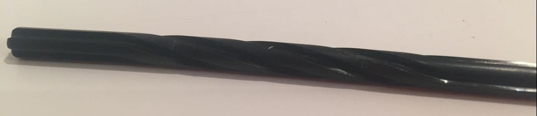
Plastic LEGO axle permanently twisted by a LEGO XL motor geared down by a 5:1 ratio
With some walkers the gait is smooth enough and the weight low enough that axle twisting doesn't harm the gait much. However, with heavy and wide walkers, like the Mindstorms TrotBot I just finished, axle twisting can be a problem. Fortunately, Brick Machine Shop makes stainless steel axles for LEGO: 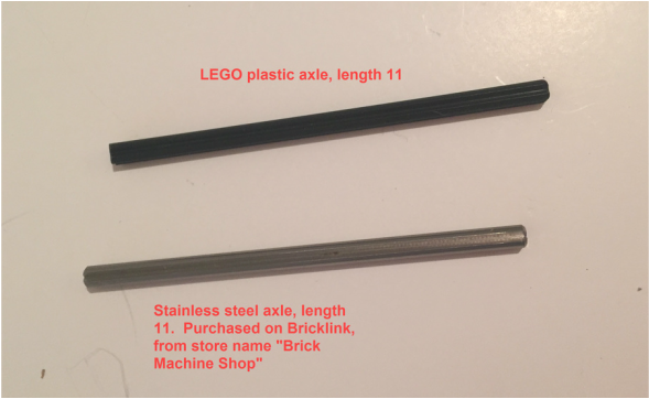
These steel axles resist twisting and help to keep leg movement closer to the mechanism's designed movement. They also fit more tightly, so cranks won't come off axles while operating your walker - but this also means it is difficult to insert these axles into parts, so we pre-stretch the LEGO holes before putting the parts onto the robot (see below). We also use a Kapla block, coin or needle nose pliers to make it easier to remove parts from the axles. Pre-Stretching LEGO axle holes: 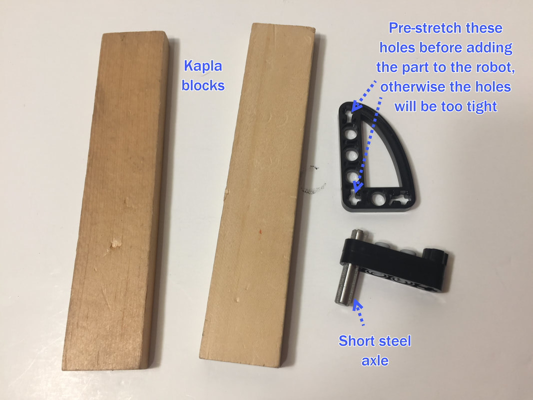
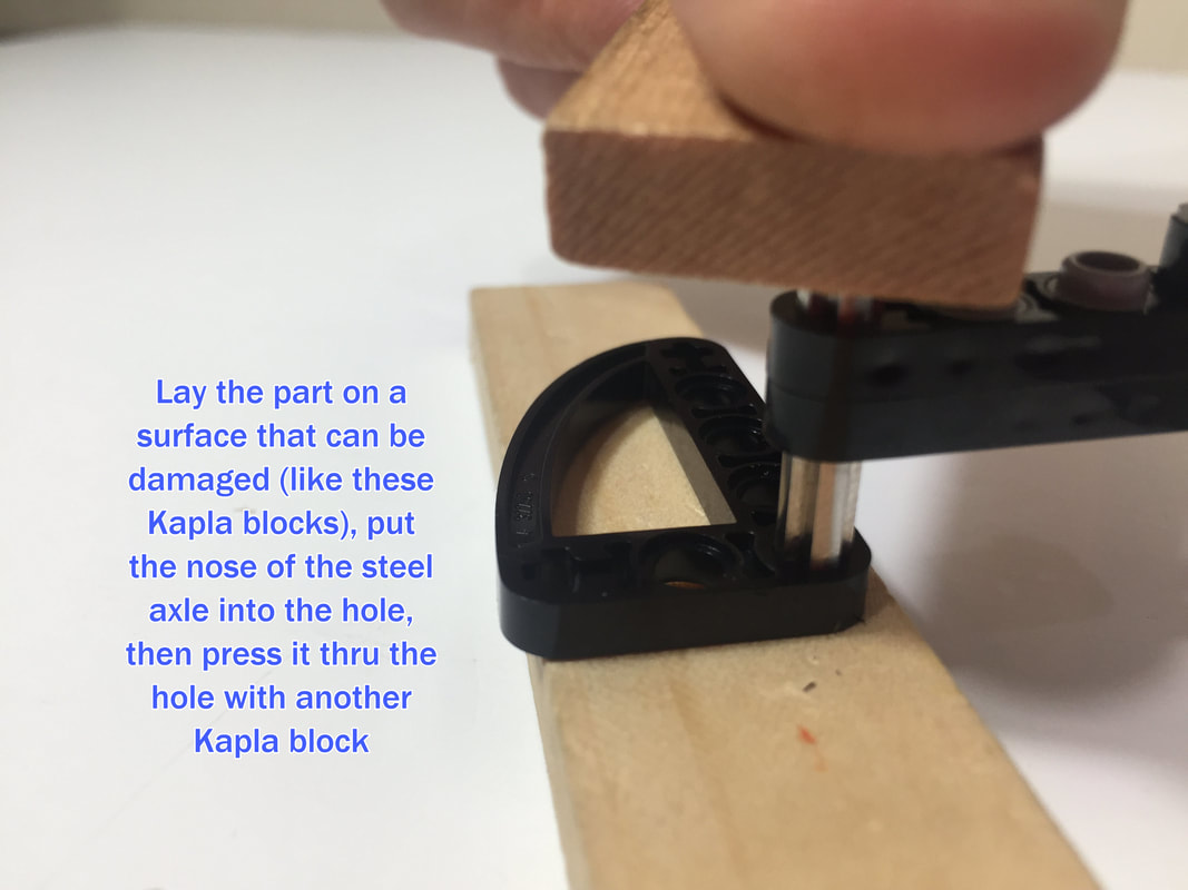
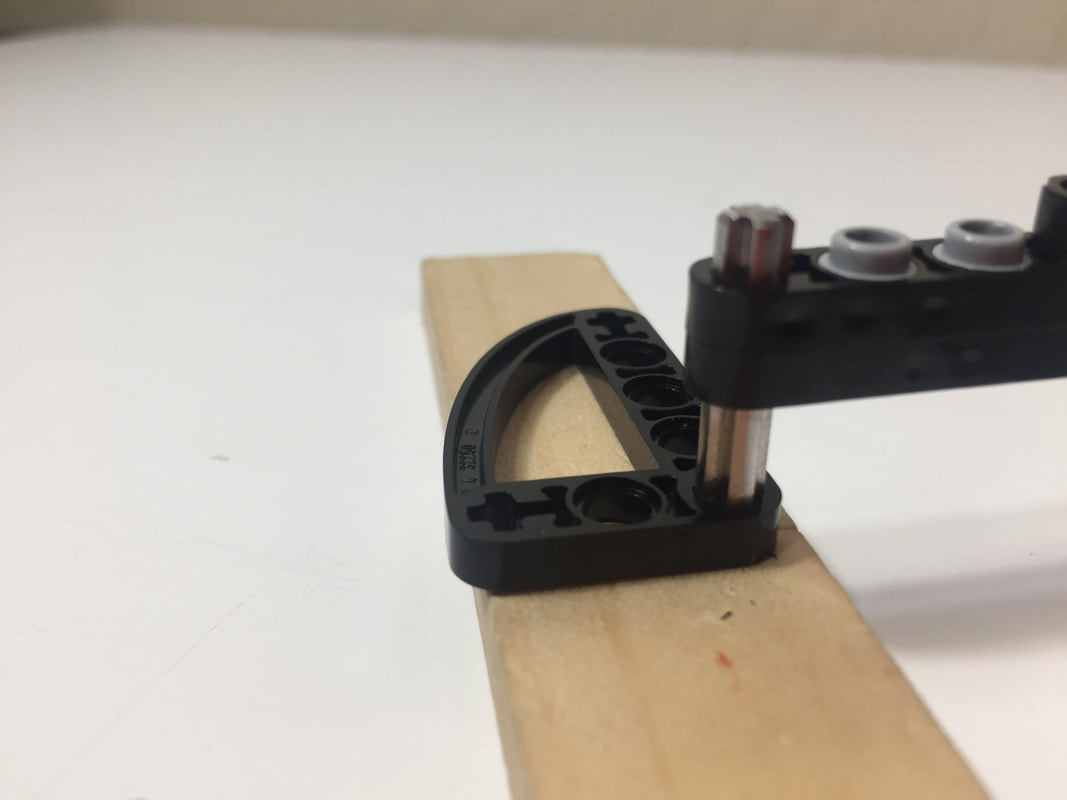
Then, slide the part up and down the axle a couple times to widen the hole a bit more, using something like a Kapla block, coin, or needle nose pliers to increase your leverage.
We purchased these steel axles from former Bricklink store Brick Machine Shop. UPDATE: Brick Machine Shop is no longer on Bricklink, but you can find them on Ebay under the store name "CNCgear" |
Categories
All
Archives
February 2023
|
 RSS Feed