4-Bar Linkage Optimizer
Posted by Ben and Wade
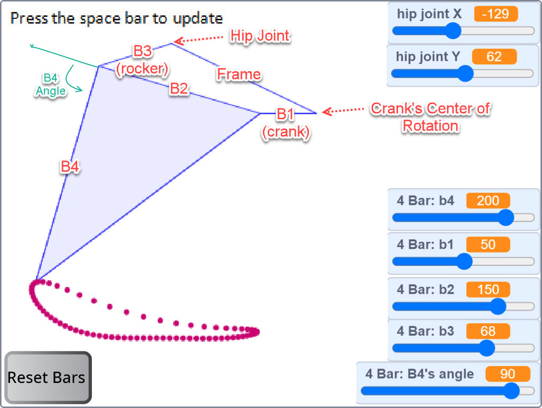
This linkage simulator allows you to quickly check how changing the linkage's bar lengths affect the path it draws as the crank is rotated.
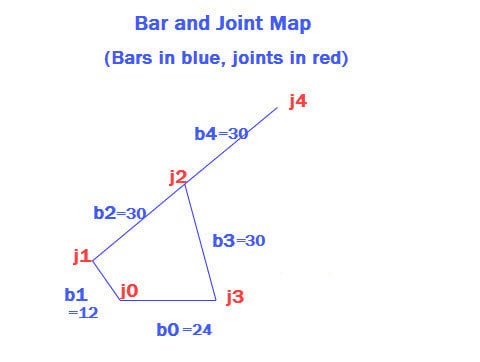
The bar map below shows 5 bars, b0 thru b4, but since the angle between b2 and b4 is fixed, j1 thru j4 is considered a single bar. Also, the frame functions as a bar of the linkage, with frame connections j0 and j3 creating bar b0.
Below is an interactive simulator which is started by clicking the green flag. You can also run the simulator on MIT's site where you can modify the code.
After changing a bar's length, click somewhere other than a slider bar and then press the space bar to see the new linkage, and use your keyboard's left/right arrows to rotate the crank.
When building a simulated linkage in LEGO, remember to use beams with one more hole than the bar's length. For example, a bar of length 8 requires a LEGO beam with 9 holes, because when determining the length of LEGO beams, the first hole is always counted as zero.
A description of the algorithms, and how we used them to simulate linkages, is here.
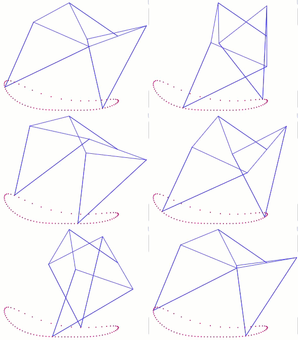
Below are some of the major categories of 4-bar linkage behavior, created by re-arranging the yellow, white, orange and red bars:
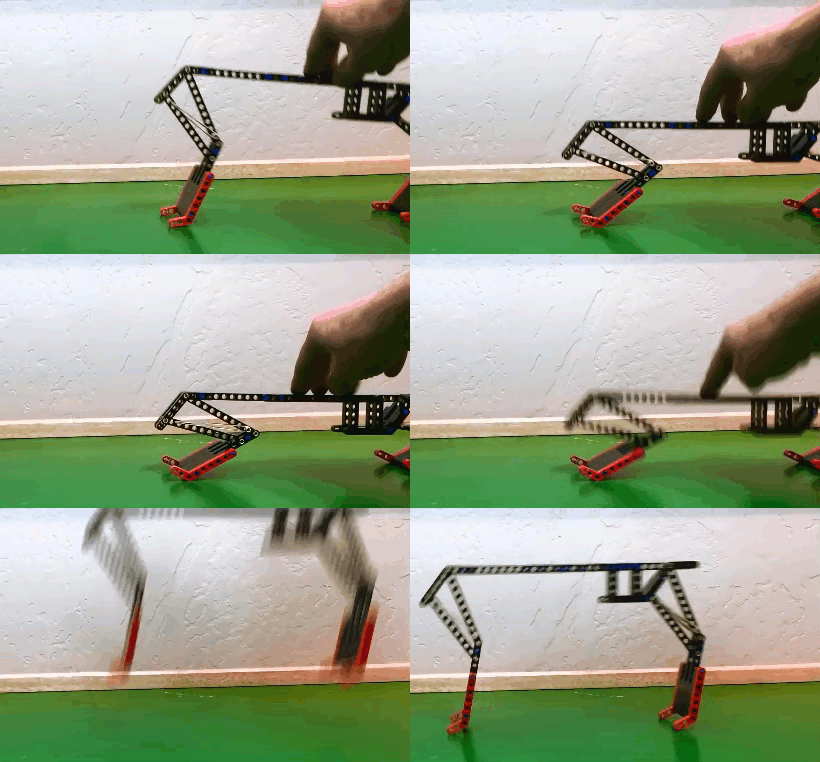
4-bar linkages configured to have a crank and rocker can be used to make simple, sturdy and efficient mechanical legs like below, which can be modified on our 4-Bar Walking Linkage Optimizer page.
4-bar linkages configured to have a crank and rocker can be used to make simple, sturdy and efficient mechanical legs like below, which can be modified on our 4-Bar Walking Linkage Optimizer page.
4-bar linkages can also serve as a starting point for making more complicated mechanisms with improved features, like Strider's paired-leg, 10-bar linkage below which we originally made by linking two 4-bar linkages:
Evolution has also found 4-bar linkages to be useful for knee joints:
Evolution has also found 4-bar linkages to be useful for knee joints:
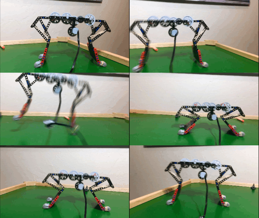
4-bar linkages can be used to create robotic arms and legs in numerous ways. Below is a feasibility test of a hopping robot based on a 4-bar linkage configured to have two rocker bars (so zero cranks).
And for a fun classroom activity for introducing 4-bar linkages, see LEGO Punchers:
These punchers can also be motorized, but this requires converting the circular motion of the motor to oscillation. This can be done by programming a servo motor to do a partial rotation, or by adding a crank and a 6th bar to the mechanism as done in the following video:

