Strider Linkage Optimizer

Strider Linkage Variation 7
Posted by Wade
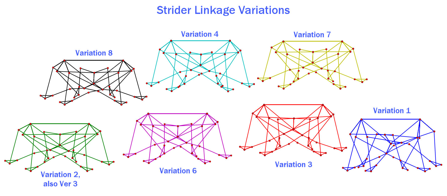
Here are the variations of Strider's linkage explored on this page, and there is also an interactive simulator at the bottom of this page.
Here are the variations of Strider's linkage explored on this page, and there is also an interactive simulator at the bottom of this page.
Below simulates Strider Ver 3's linkage, which is explored further down as Variation 2
To increase step-height, Strider's linkage pairs two 4-bar linkages into a combined 10-bar linkage with front and back legs, such that an extended bar of the rear leg lifts the front foot, and vice versa
The simulation above doesn't have toes, but Striders tend to walk slightly more smoothly with toes that are 2 units long, angled at 125.7 degrees relative to the leg's inner bar. These are the toes that are simulated in the following video:
For a smoother gait, Strider should be built with 12 legs, so the following simulations are of one side of 12-legged Striders, with the speed and height set by the robot's front legs.
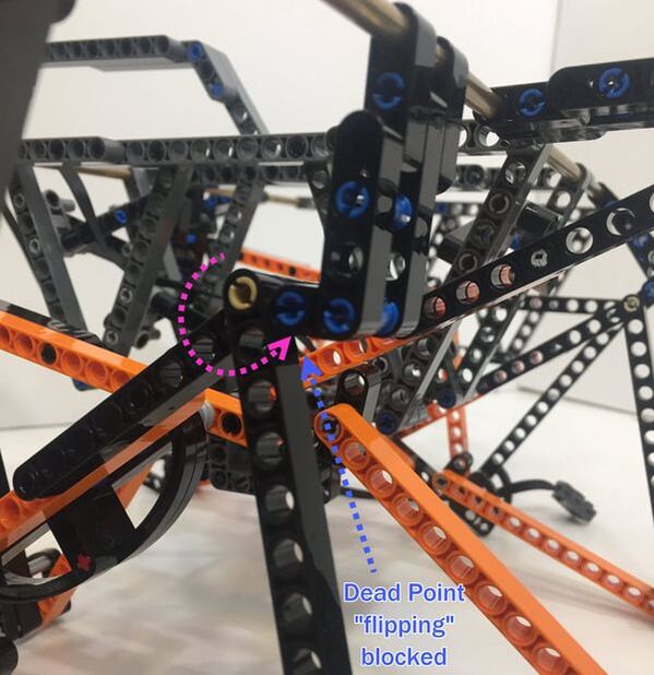
The simulations were made in Python, but there is also an interactive Scratch-based simulator at the bottom of this page. Note: some of the simulated versions on this page haven't been tested in LEGO yet, and they may not work well, at least not without some tinkering, such as managing Strider's Dead Point (it's a lot easier to simulate new mechanisms than it is to build functional versions of them!)
For a smoother gait, Strider should be built with 12 legs, so the following simulations are of one side of 12-legged Striders, with the speed and height set by the robot's front legs.
The simulations were made in Python, but there is also an interactive Scratch-based simulator at the bottom of this page. Note: some of the simulated versions on this page haven't been tested in LEGO yet, and they may not work well, at least not without some tinkering, such as managing Strider's Dead Point (it's a lot easier to simulate new mechanisms than it is to build functional versions of them!)
Strider Ver 2
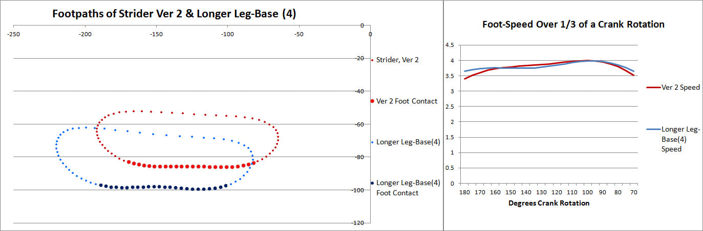
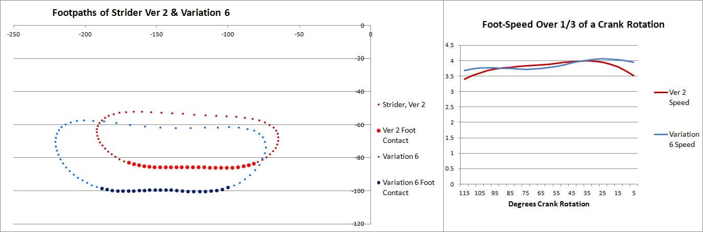
To start, here's Strider Ver 2's linkage, who's foot-path is compared to each linkage variation below as a sort of benchmark.
Strider Ver 2
To start, here's Strider Ver 2's linkage, who's foot-path is compared to each linkage variation below as a sort of benchmark.
|
|
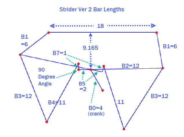
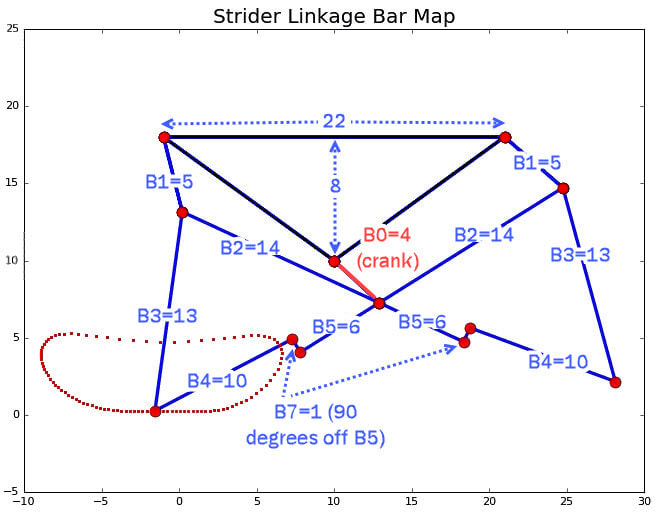
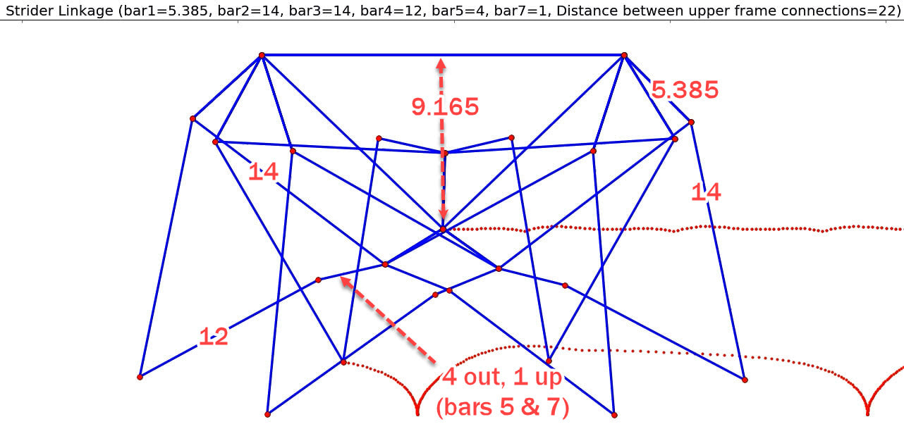
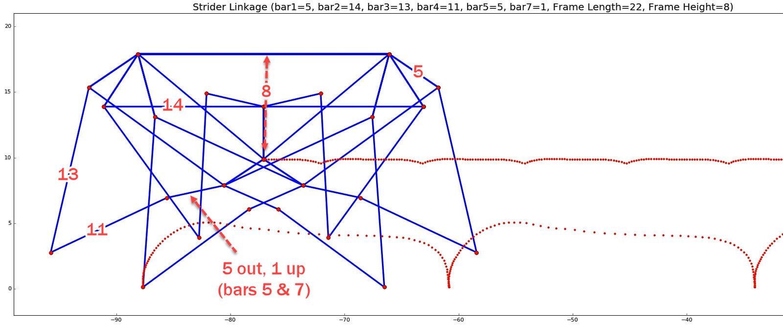
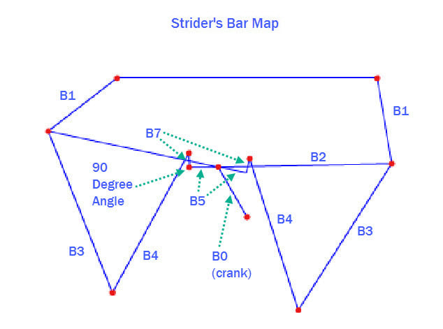
In the following simulations the bar lengths are displayed at the top of the images, like in the image below:
In the following simulations the bar lengths are displayed at the top of the images, like in the image below:
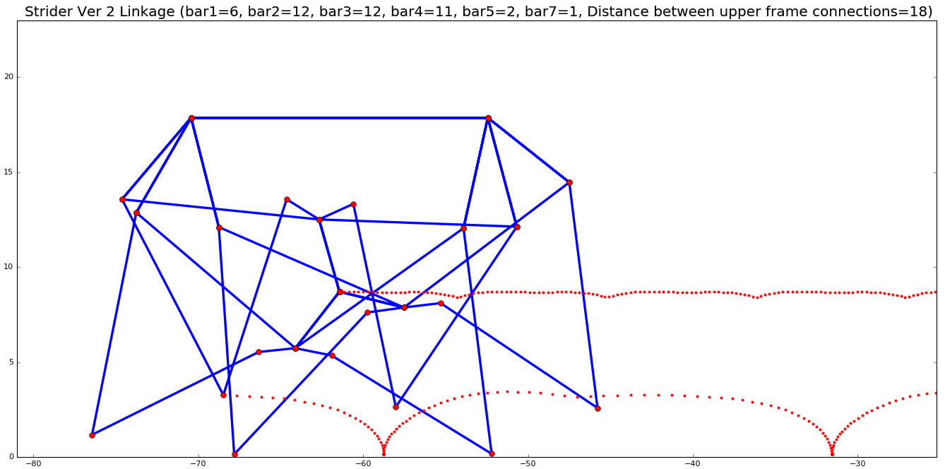
Strider, Ver 2
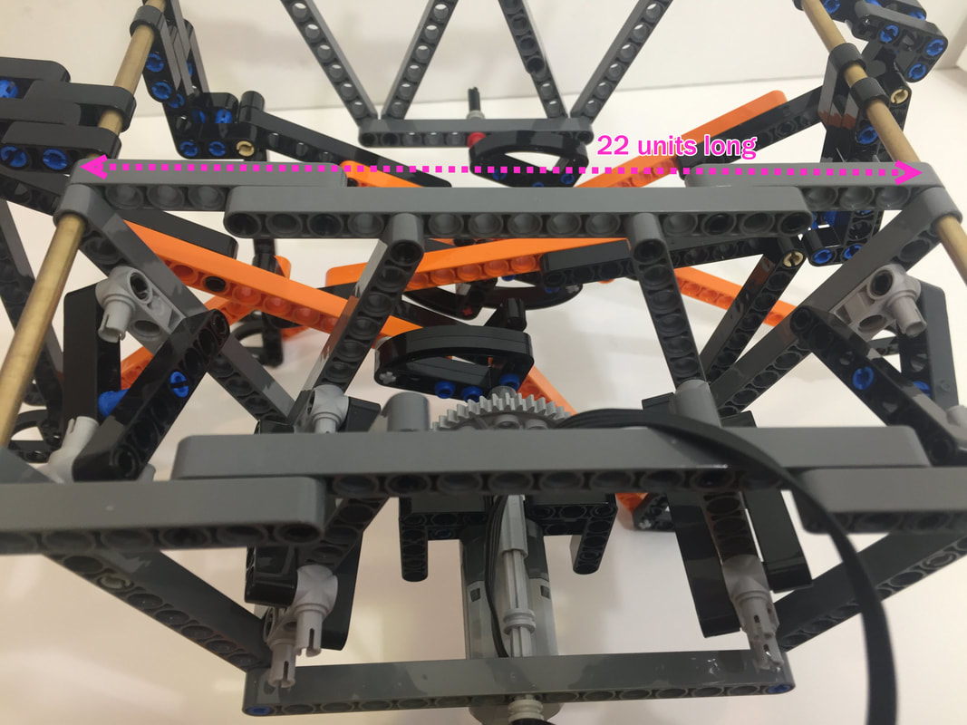
Strider Ver 2 has a short leg-base, which makes it prone to flipping backward when climbing. The variations explored on this page lengthen Strider's leg-base by moving the X positions of the upper frame connections two units further from the crank, expanding the distance between them from 18 to 22 as shown in the image below.
Strider Variation 4's inner frame. Frame length= 22, frame height = 9.165
Note: LEGO's integer-based beams can make it tricky to find diagonal beams of the correct length to strengthen frames. You can find some ideas for creating strong, triangle-based frames in LEGO here.
LEGO-Friendly Variations of Strider's Linkage
Variation 1
.....has gone back to the drawing board
LEGO-Friendly Variations of Strider's Linkage
Variation 1
.....has gone back to the drawing board
Variation 2 (Version 3 in LEGO)
Variation 2 was optimized for a higher step, and is the variation used for Strider Ver 3:
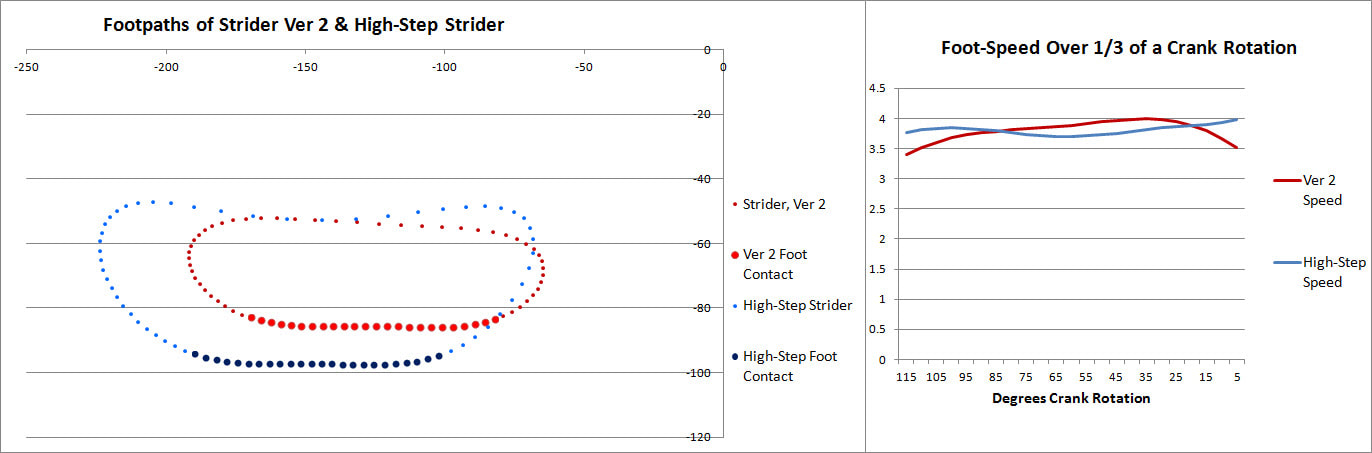
Note: For all the variations of Strider analyzed on this page, the foot-speed plotted in the above right graph is the speed without adding toes. It's calculated every 5 degrees of crank rotation as follows:
Foot-Speed (crank at x degrees) = Foot's X position(crank at x degrees) - Foot's X position(crank at x-5 degrees)
To do your own speed calculations, you can download the foot joint's X,Y data from the simulators at the bottom of this page, as described in our Scratch instructions.
Notice in the below image that when the foot touching the ground transitions to the next foot there is a bump in the gait, which can be smoothed by adding toes with a length of 2 units, angled at 125.7 degrees relative to the leg's inner bar, which are simulated in the animated GIFs below.
Strider Linkage Variation 2 (also Ver 3)
The LEGO version of Strider Ver 3 can be smoothed with the slightly more refined linkage simulated below, the dimensions of which are below the GIF.
Strider Linkage Variation 2 (also Ver 3)
|
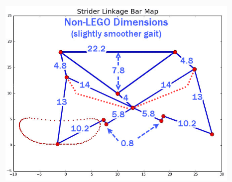
Smoother, Non-LEGO Strider Ver 3. Note: bar B2 of length 14 should be made with a bend like the red dotted lines so they do not hit the support rods (the top corners)
|
Also, the gaits of larger-scale Striders can be further smoothed by adding shock-absorbing pads to the bottom of the feet, which is explored in this blog post on shock-absorbing feet.
Here's Variation 2 prototyped in LEGO (Strider Ver 3) with the above simulated toes, and geared down for climbing:
And here's Variation 2 (ver 3) with 8 legs plus shock-absorbing heels:
Variation 3
.....has gone back to the drawing board
Variation 3
.....has gone back to the drawing board
Variation 4
Variation 4
Strider Linkage Variation 4 ( frame height = 9.165)
Here's a quick test of Variation 4, prototyped in LEGO with 8 legs instead of 12. Toes were added to smooth the gait a bit, but rather than mounting the toes to the front of the "shin", they should have been mounted to the inside beam of the leg, like how Strider Ver 3's toes are mounted - see the simulation below the video.
Below simulates Variation 4 with the toes of length 2 added to the inside beam of the legs, like how Strider Ver 3's toes are mounted:
Side Comment on Frame Heights and Fine Tuning Linkages with Irregular-Length Parts
Below shows some LEGO beam lengths for creating frames of a few different heights. NOTE: the LEGO beams used to make these triangles have one more hole than the sides of the triangles, since when determining the length of LEGO beams, the first hole is always counted as zero.
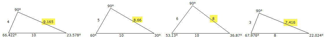
LEGO beam lengths for creating frames of varying heights
You can find other ideas for creating strong, triangle-based frames in LEGO here.
|
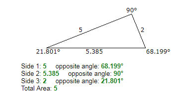
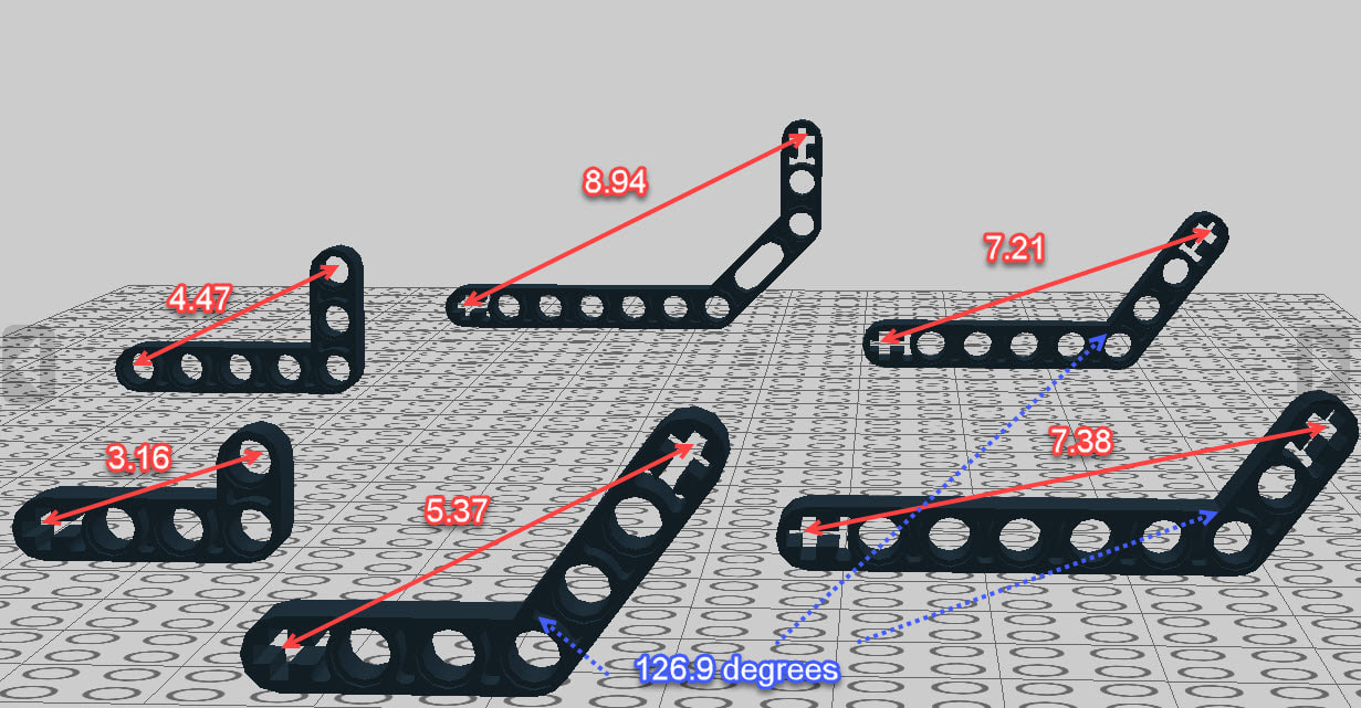
Irregular-Length Parts
Linkages can be fine-tuned in LEGO by utilizing LEGO's angled parts to create bars of irregular lengths. For example, variation 4's upper bar B1 was set equal to 5.385. B1 is the bar above the knee (the femur or rocker bar). This part length is created in LEGO by attaching a beam to a 3x5 L-shaped part to make a 3x6 L-shaped part with a hypotenuse of length 5.385, as shown in the image to the right. An online triangle calculator is here. |
|
Variation 4 with its 3x6 L-shaped "Femur"
|
|
Other examples of managing Dead Points are shown here.
Lengths of LEGO's bent beams in units of LEGO beam holes
Variation 5
.....has gone back to the drawing board
Variation 5
.....has gone back to the drawing board
In all the following variations the toes have a length of 2 units with an angle of 125.7 degrees relative to the leg's inner bar, just like Strider Ver 3's toes.
Variation 6
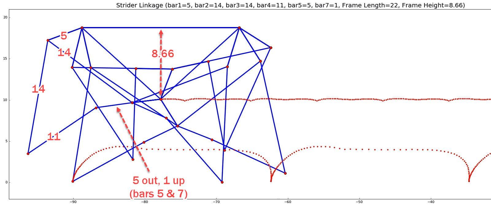
Strider Linkage Variation 6 ( frame height = 8.66)
Variation 6 has the least amount of up/down movement, as indicated by how flat its red center line is in the above GIF. While this improvement may be subtle with LEGO builds, it can make a big difference at large scales, or when loads are added. In our tests, Variation 6 was the only variation capable of carrying a 25 pound load (see video below).
Here's Variation 6 walking passively down an inclined plane for this Dead Point experiment:
Notice how the robot wavers slightly to the left and right as it descends, due to the foot-speed varying a little.
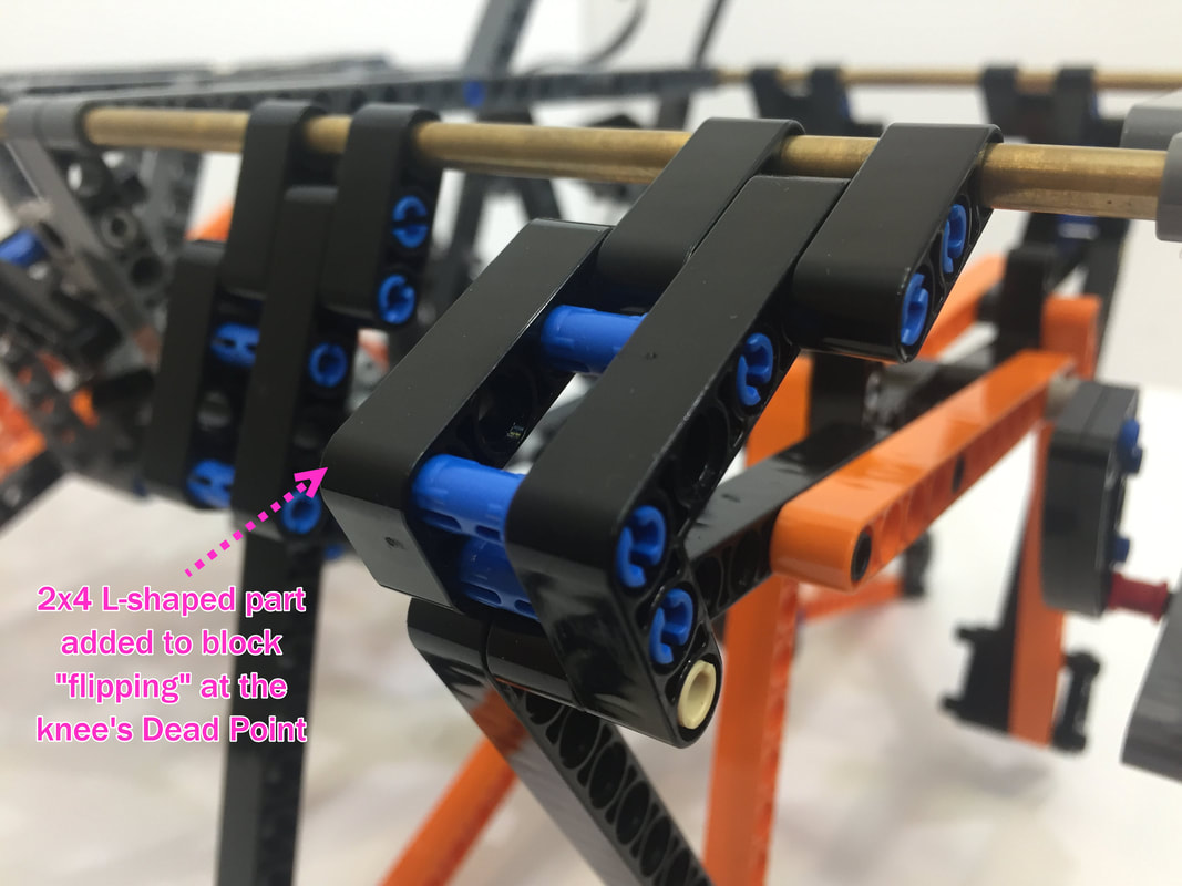
Variation 6 results in the least up/down movement of the robot, which means motor power doesn't have to wasted by raising and lowering the robot's weight repeatedly. We tested the impact of this by adding a 25 pound load to Variation 6, as well as Variation 7 and Strider Ver 3, and the LEGO motors quickly stalled with both Variation 7 and Ver 3. However, it was an imperfect test since we didn't add the knee hyper-extension blockers like we added to the knees of Variation 6 below, which may have also played a role in the motors stalling.
Variation 6 results in the least up/down movement of the robot, which means motor power doesn't have to wasted by raising and lowering the robot's weight repeatedly. We tested the impact of this by adding a 25 pound load to Variation 6, as well as Variation 7 and Strider Ver 3, and the LEGO motors quickly stalled with both Variation 7 and Ver 3. However, it was an imperfect test since we didn't add the knee hyper-extension blockers like we added to the knees of Variation 6 below, which may have also played a role in the motors stalling.
Before performing this test, the plastic LEGO axles were replaced with steel axles to handle the torque. Other than that, and the 2 steel support rods, all of the parts are plastic LEGO parts connected by LEGO pins (no glue).
Before performing this test, the plastic LEGO axles were replaced with steel axles to handle the torque. Other than that, and the 2 steel support rods, all of the parts are plastic LEGO parts connected by LEGO pins (no glue).
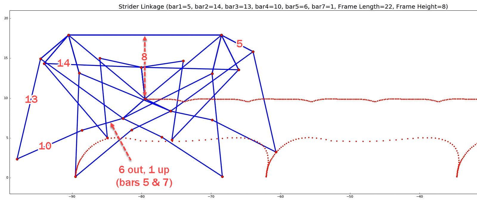
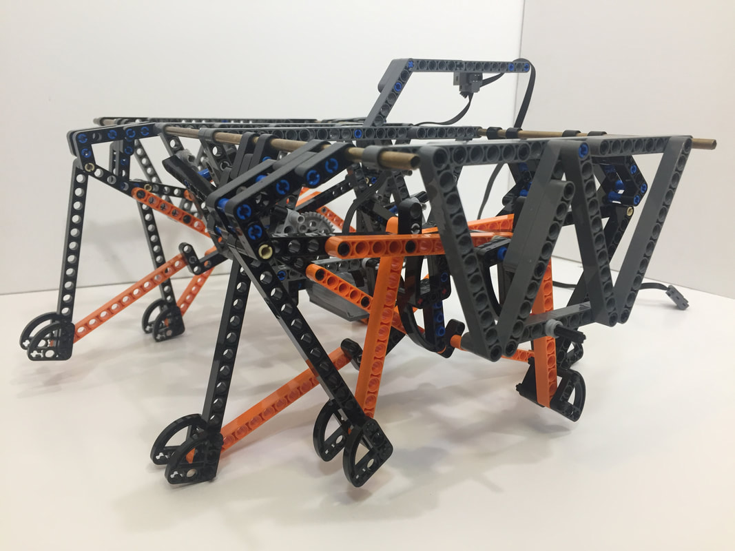
Variation 7
Variation 7 is a close cousin of Ver 3. It doesn't step quite as high on the inside of its foot-path, but it has more consistent speed when its toes are taken into account. It uses the same frame as Ver 3, and only differs by shortening the "hamstring" (Bar5) from 6 to 5, and by lengthening the "calf" (Bar4) from 10 to 11.
Strider Linkage Variation 7 ( frame height = 8)
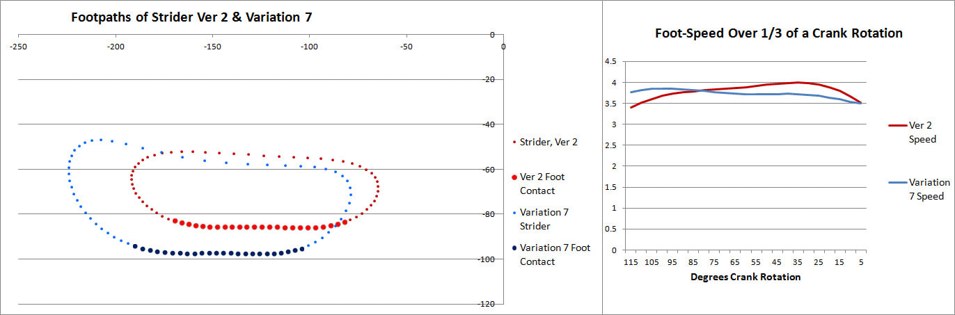
While Variation 7's speed drops slightly on the right side of the speed chart, that's because it's a plot of the speed of the center of the foot's joint J4, and it doesn't take the foot's rotation into account - which can make a big difference when toes are added. When the foot's rotation is included in the speed calculation, variation 7 has the most consistent speed of all of these LEGO-friendly versions of Strider, as shown by how little the feet skid in the following video:
The tests above use LEGO's XL motors geared up to a 1:1 ratio, and the test below uses a more practical 5:3 gear ratio.
|
Variation 7's consistent foot-speed makes it efficient at walking passively since the feet skid less. This can be done with wind, gravity, or by pushing/pulling the robot as done in the video below: |
|
Variation 8
.....has gone back to the drawing board
Strider Linkage Optimizer
You can quickly check how changing Strider's bar lengths affect its foot-path with the below simulator, but remember, just because something looks good in a simulation doesn't necessarily mean it will work well when built - at least not without some tinkering. Also, Strider's knee joint will flip at its dead point if your build doesn't prevent it.
First, here's a video of a simulator in action - three interactive simulators are further down.
Below are the Scratch-based simulators. You can also run the simulators on MIT's site where you can access and modify the code.
|
|
After changing a bar's length, click somewhere other than a slider bar and then press the space bar to see the new linkage and foot-path, and use your keyboard's left/right arrows to rotate the crank.
Here's the simulator for LEGO-friendly bar lengths which is started by clicking the green flag. To more finely tune Strider's linkage you can find a Bars X 10 version further down.
Here's the simulator for LEGO-friendly bar lengths which is started by clicking the green flag. To more finely tune Strider's linkage you can find a Bars X 10 version further down.
Below is a 2-leg version:
Below is the Bars X 10 version (with toes) to more finely tune Strider's linkage: