TrotBot Linkage Optimizer
Posted by Ben and Wade
This simulator allows you to quickly check how changing TrotBot's bar lengths affect its foot-path, but remember, just because something looks good in a simulation doesn't guarantee it will work well when built - at least not without some tinkering, such as managing possible dead points. You can see an obvious dead point in the "TrotBot Linkage Optimizer" video's 3rd configuration (the video on the left).
TrotBot's heel and toe linkage dimensions can be found here, along with a summary of TrotBot's development.
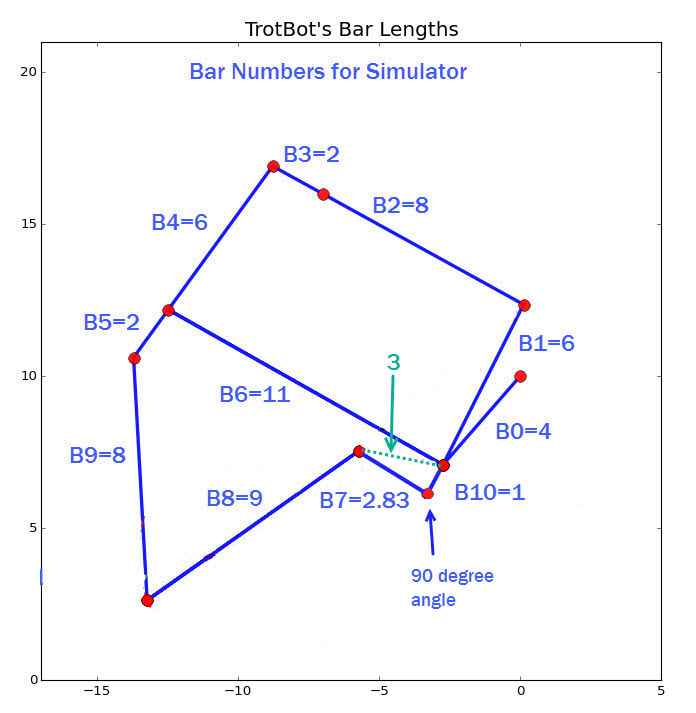
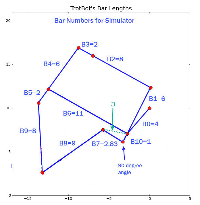
TrotBot's linkage in LEGO on the right only differs from the non-LEGO TrotBot by having bar B7 connect one hole below the crank. Another way of illustrating the difference is: if the non-LEGO TrotBot's bar B7 were connected one hole below the crank (like it is in LEGO), then it's length would need to be shortened from 3 to 2.83 (as shown in the image below)
|
|
|
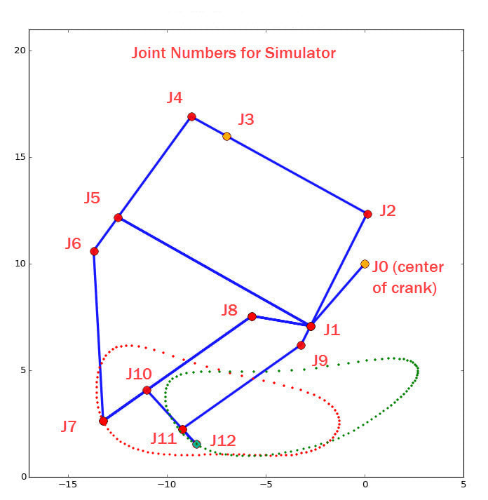
Above are the bar and joint maps used in TrotBot's Scratch and Python code, which you can download here.
Below are the interactive simulators. You can also run the simulators on MIT's site where you can access and modify the Scratch code.
Note: the "HiFrameX" and "HiFrameY" variables are the horizontal and vertical distances from the frame connection to the center of the crank.
For efficient gaits, TrotBot's without "heels" should probably be built with 12 legs so that at least one foot is in contact with the ground at each corner of the robot. To see why, notice when TrotBot's heels are removed in this video the feet skid, and the resulting bumpier gait requires too much power for TrotBot to carry the 10 pound load.
Below plots TrotBot's foot-path and foot-speed, assuming 12 legs.
To make it easier to check TrotBot's foot-contact at each corner, use the below 12-leg simulator. The simulator with front+back legs is further down.
Start the simulator by clicking the green flag. After changing a bar's length, click somewhere other than a slider bar and then press the space bar to see the new linkage and foot-path, and use your keyboard's left/right arrows to rotate the crank.
Start the simulator by clicking the green flag. After changing a bar's length, click somewhere other than a slider bar and then press the space bar to see the new linkage and foot-path, and use your keyboard's left/right arrows to rotate the crank.
When building a simulated linkage in LEGO, remember to use beams with one more hole than the bar's length. For example, a bar of length 8 requires a LEGO beam with 9 holes, because when determining the length of LEGO beams, the first hole is always counted as zero.


