TrotBot, ver 3
Version 3 adds options for retractable toes and greater speed, lowers the center of gravity for better climbing performance, and uses the stronger leg attachments described in this post which allow TrotBot to turn on high-friction terrain without the leg's pins coming out - the below video is an example.
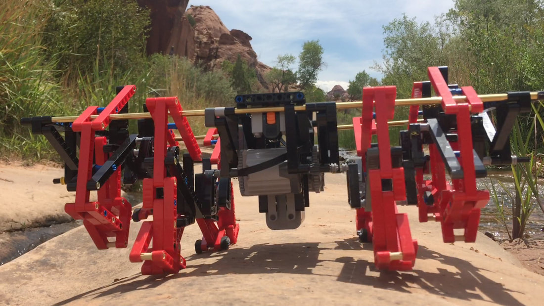
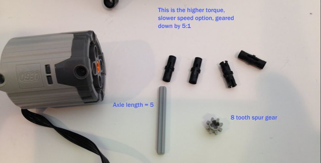
TrotBot in the above video uses the slower speed, higher torque option (geared down by 5:1). The faster speed option can be seen below in the first half of the video (geared down by 1.7:1), both with and without toes.
Below is another example of TrotBot ver 3 without toes, grinding over a couch with the help of the XL motor's power in the faster gear ratio. NOTE: when using the XL motors you may want to switch the inner legs' plastic axles to steel axles to handle the higher torque.
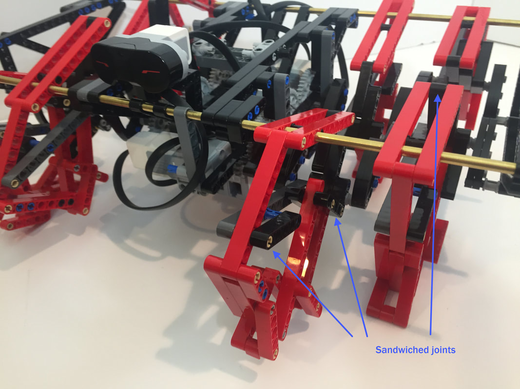
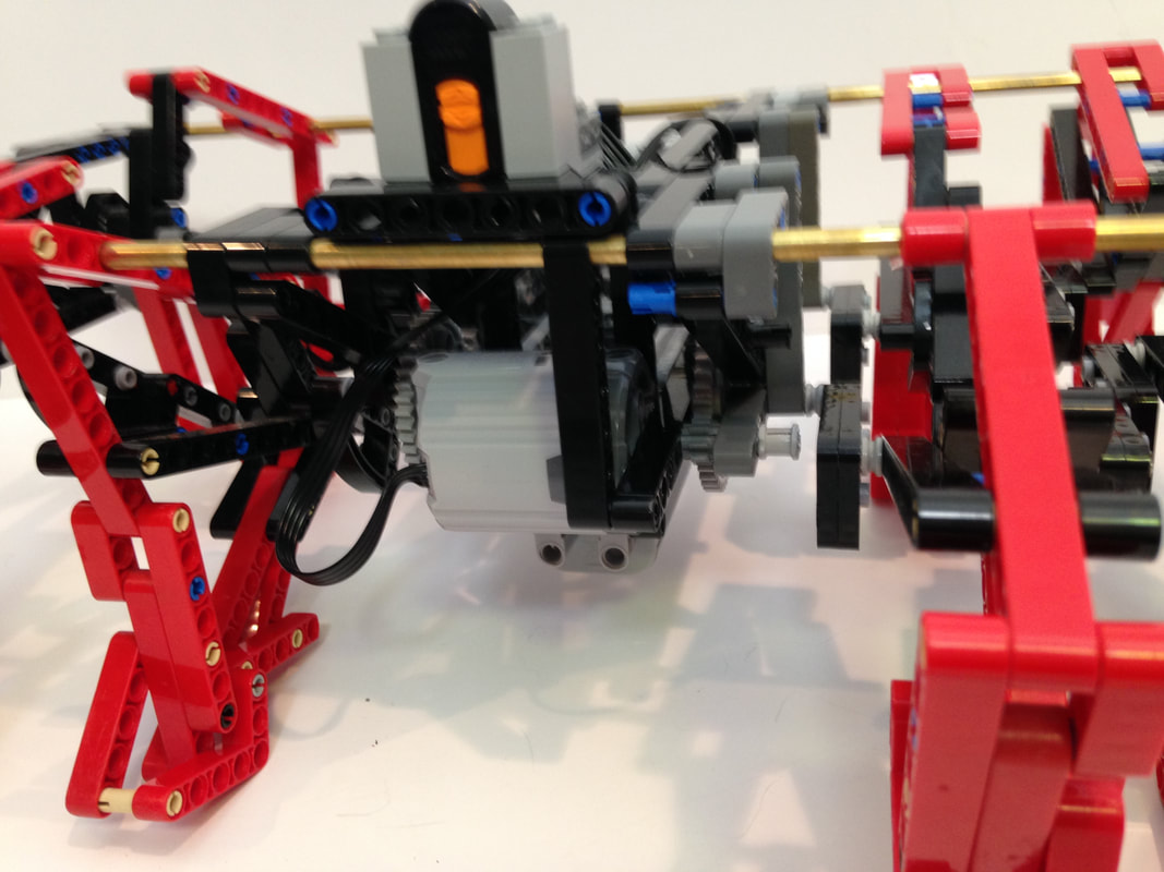
Like my Mindstorms TrotBot, Ver 3 pictured below, this build also improves a few other joints by adding a 3rd beam to sandwich them, making them symmetrical and reducing their friction/wear.
|
UPDATE: Here are some simplified instructions for building TrotBot's leg mechanism. This leg will work for all 8 legs of TrotBot. |
Simplified Instructions for Building TrotBot's Leg Mechanism
|
Let's build it!
Overview
Linkage: TrotBot uses the linkage developed by Team TrotBot
Build Difficulty: Hard.
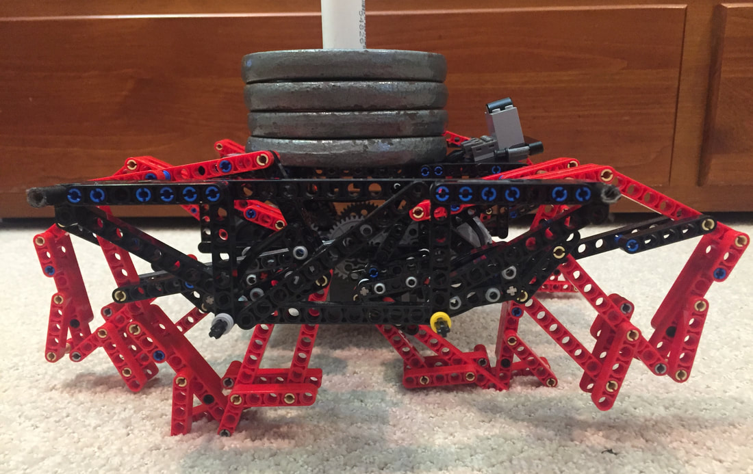
NOTE: for my weight-bearing experiment I used steel axles, but LEGO's plastic axles can be used for version 3.
Trobot's Characteristics:
1. 8 Legs with a gait that mimics a galloping horse
2. Walks most efficiently with the addition of a "heel" on both smooth and rough terrain.
3. Steerable? Yes, by driving one side forward and the other in reverse, like a tank.
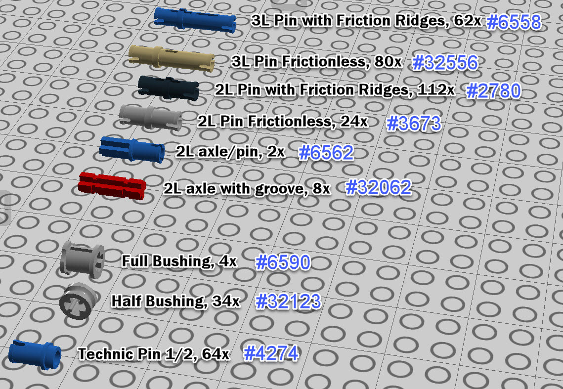
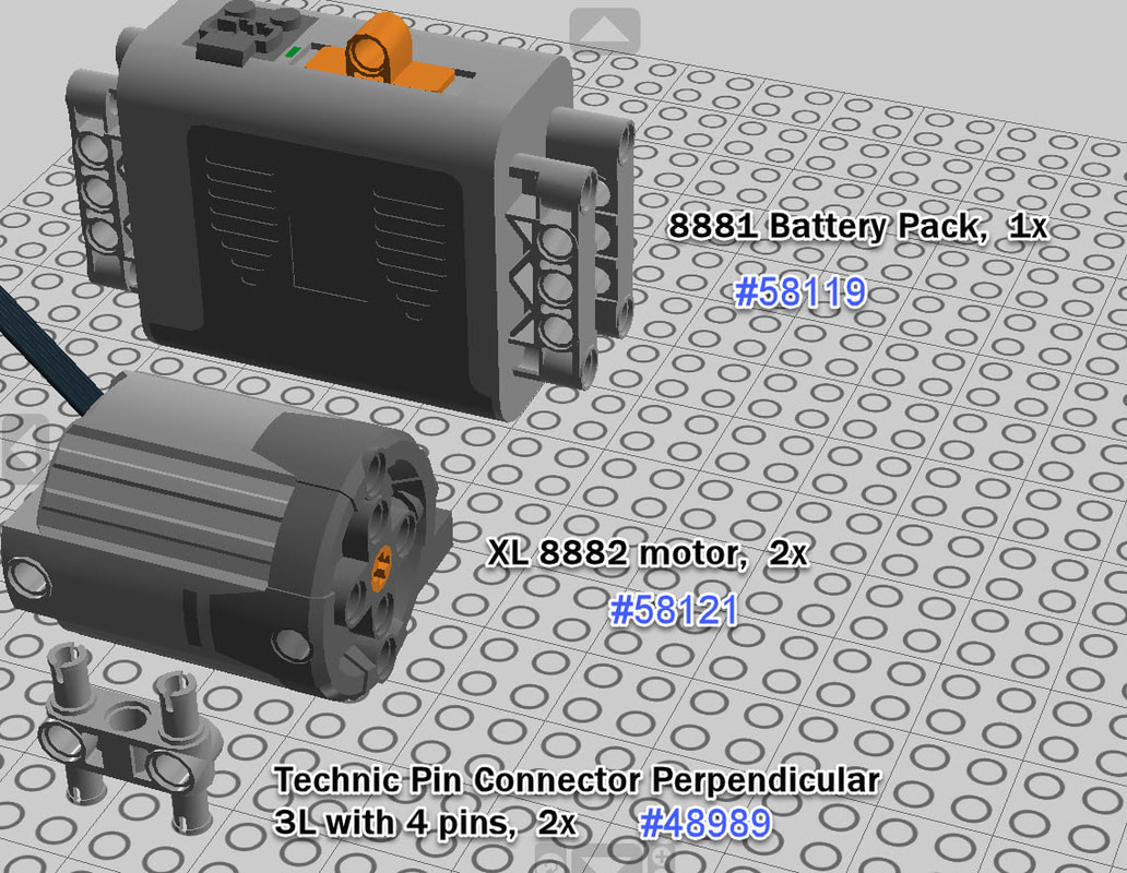
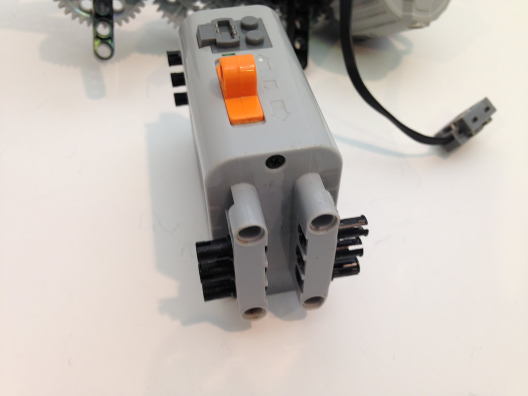
Parts Used: In addition to the Technic beams, pins, gears, etc., this build uses LEGO's Power Functions IR RX 8884 remote receiver which I controlled with a 8885 IR remote, 2 LEGO XL 8882 motors, and a 8881 Battery Pack. Also, to better bear the robot's weight I used 3/16" OD brass tubes for the leg's long connections to the frame (aluminum rods are fine too) rather than LEGO's plastic axles.
For batteries I recommend using Lithium Ion AA batteries as they are lighter, last longer, and will improve walking performance.
I purchased the plastic LEGO parts from Bricklink
I purchased the motors, controllers and battery box from Amazon
I purchased the metal support rods from my local hardware store
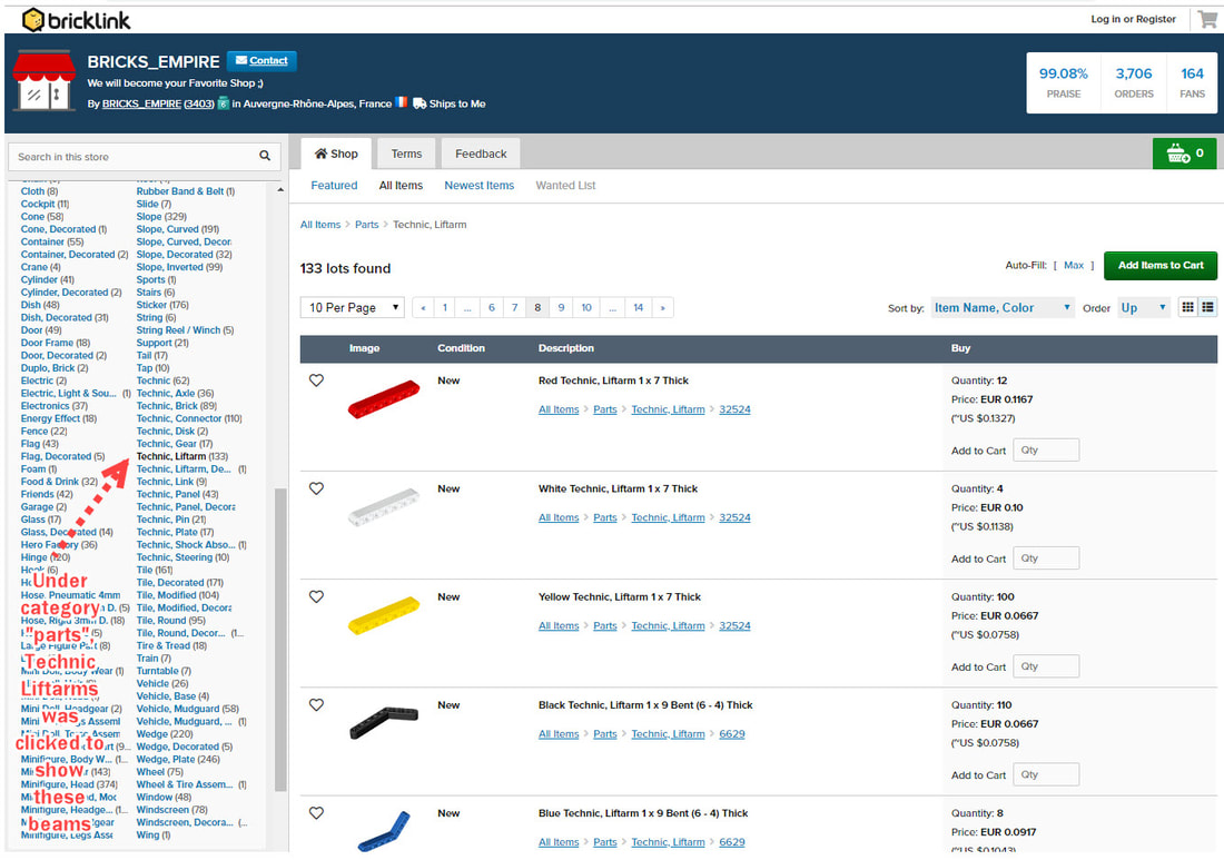
If you've never used Bricklink, an easy way to browse for parts is by going to a larger store. Here's a list of stores in the USA.
And below is an example search in a store for Technic beams.
1. 8 Legs with a gait that mimics a galloping horse
2. Walks most efficiently with the addition of a "heel" on both smooth and rough terrain.
3. Steerable? Yes, by driving one side forward and the other in reverse, like a tank.
Parts Used: In addition to the Technic beams, pins, gears, etc., this build uses LEGO's Power Functions IR RX 8884 remote receiver which I controlled with a 8885 IR remote, 2 LEGO XL 8882 motors, and a 8881 Battery Pack. Also, to better bear the robot's weight I used 3/16" OD brass tubes for the leg's long connections to the frame (aluminum rods are fine too) rather than LEGO's plastic axles.
For batteries I recommend using Lithium Ion AA batteries as they are lighter, last longer, and will improve walking performance.
I purchased the plastic LEGO parts from Bricklink
I purchased the motors, controllers and battery box from Amazon
I purchased the metal support rods from my local hardware store
If you've never used Bricklink, an easy way to browse for parts is by going to a larger store. Here's a list of stores in the USA.
And below is an example search in a store for Technic beams.
|
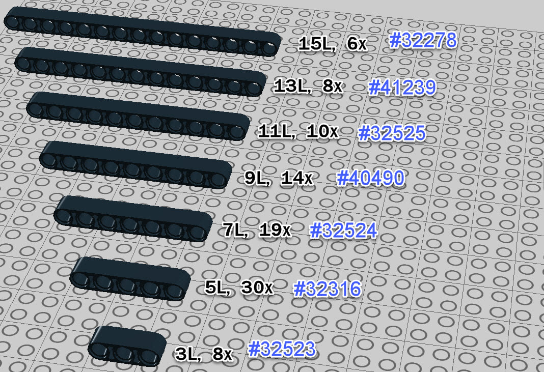
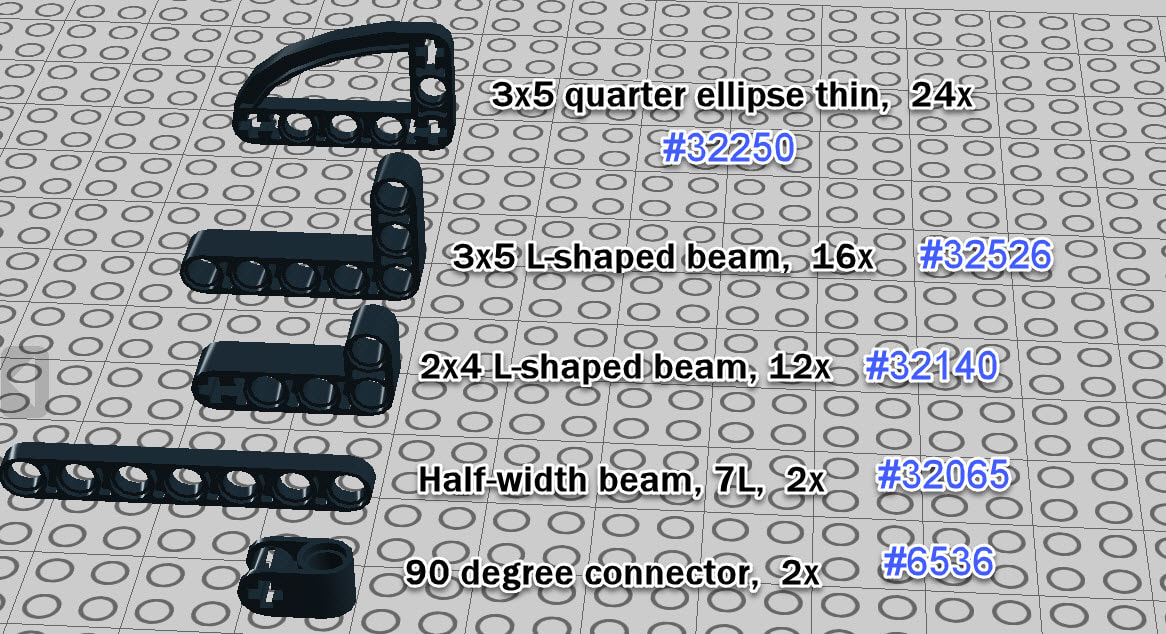
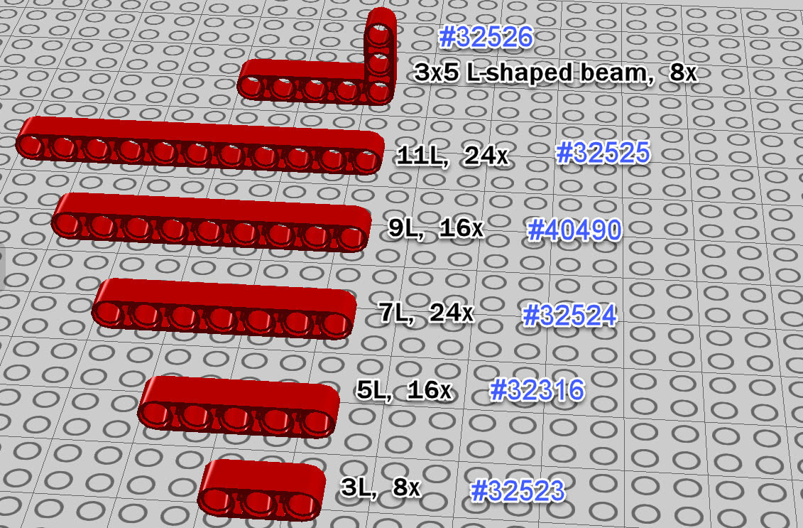
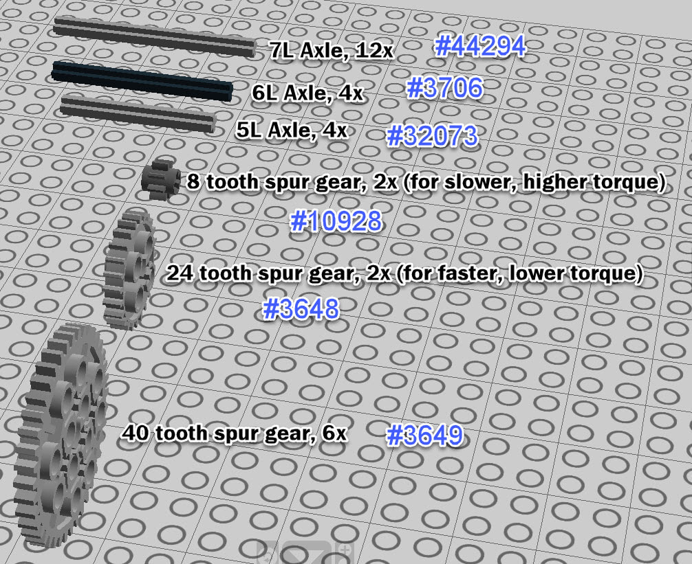
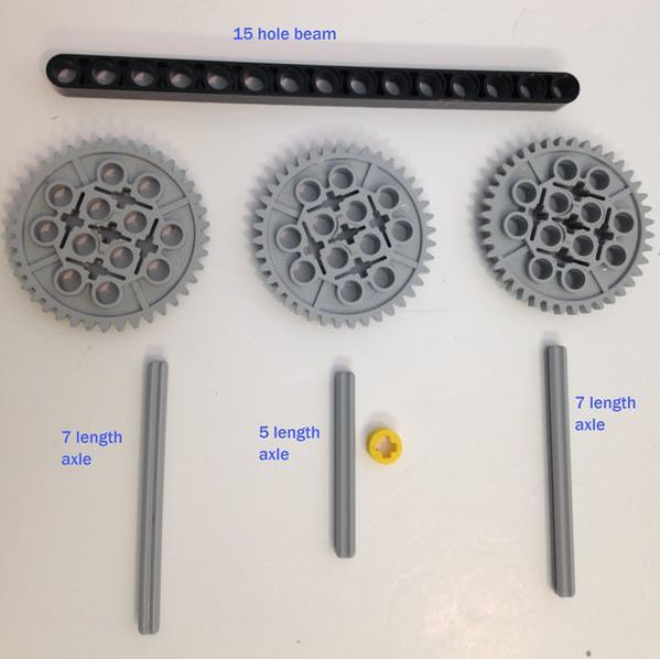
LEGO Part List:
The part list can be downloaded here, or you can view the images below. If I made any mistakes please email me at [email protected] |
| ||

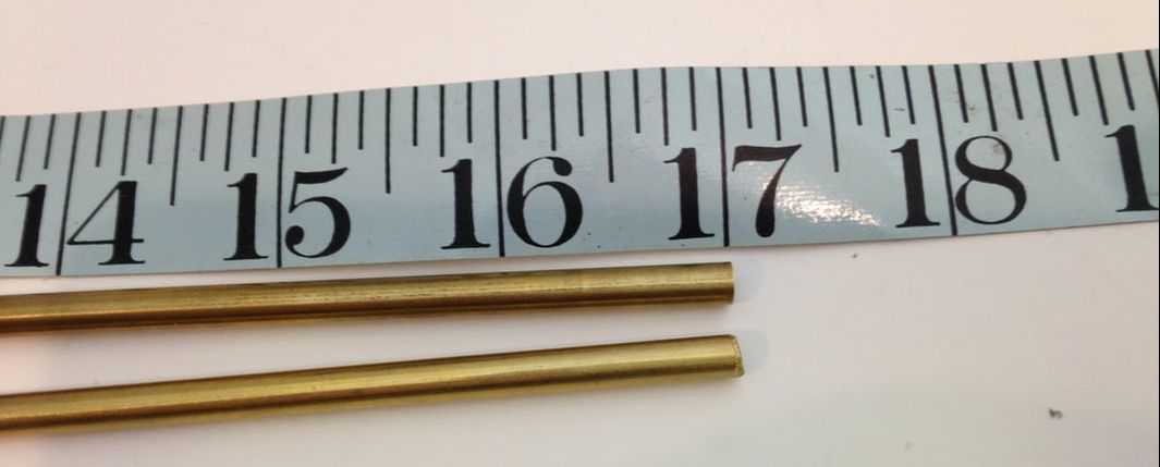
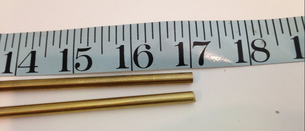
Brass tubes (or aluminium rods) cut to 17 inches in length. Be sure to file down the cut end.
Trouble Shooting a Finished TrotBot
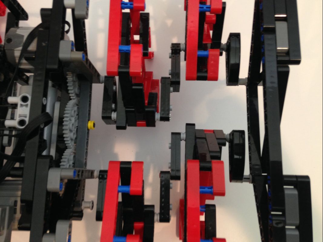
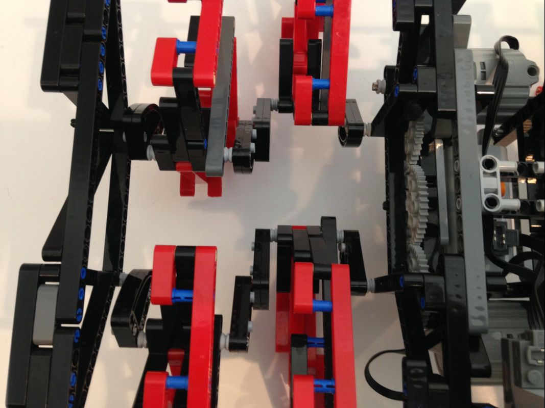
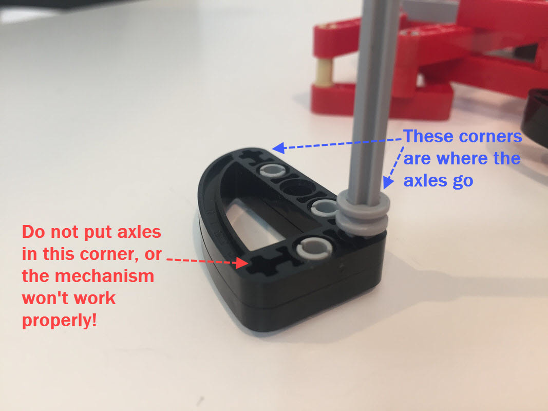
A finished TrotBot's legs should be easy to rotate by hand with the motors disengaged. If you feel resistance, then look carefully at the legs to see if any look asymmetrical or skewed. Also, an easy mistake to make is to put the axles thru the wrong hole of the 3x5 cam part below. If the legs aren't working properly, check your cranks.
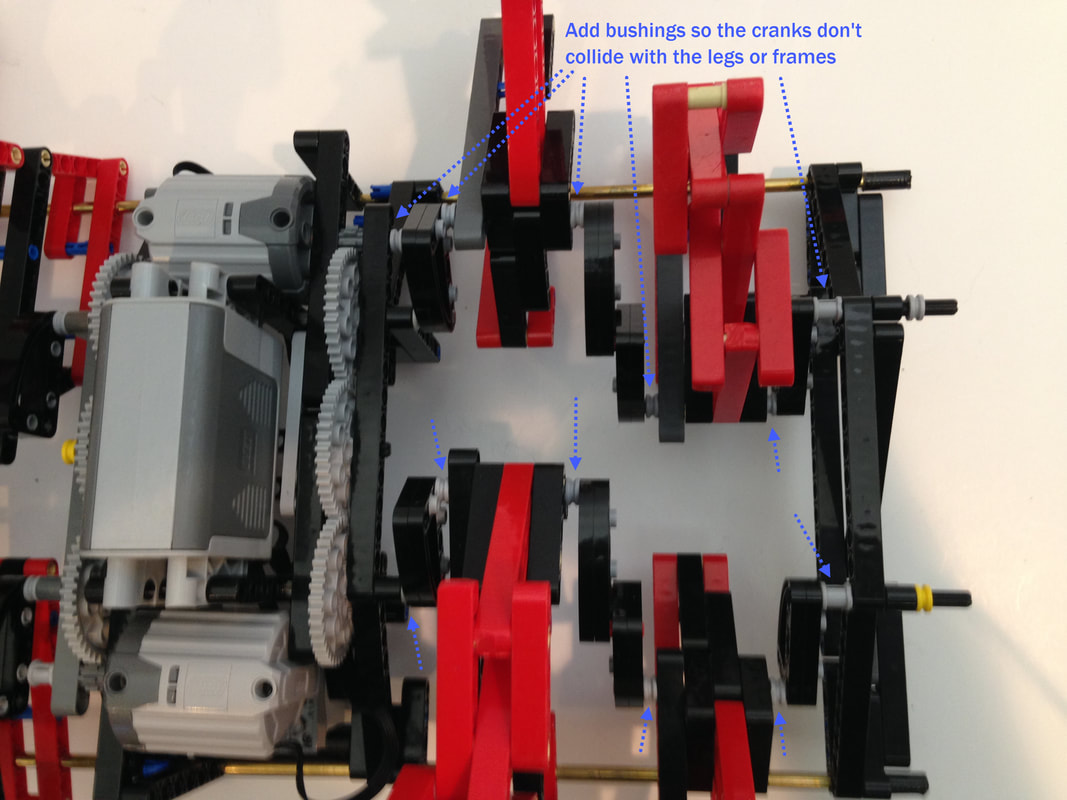
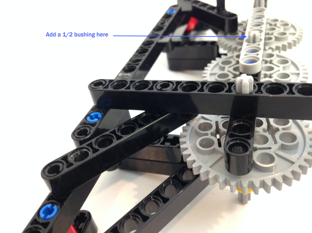
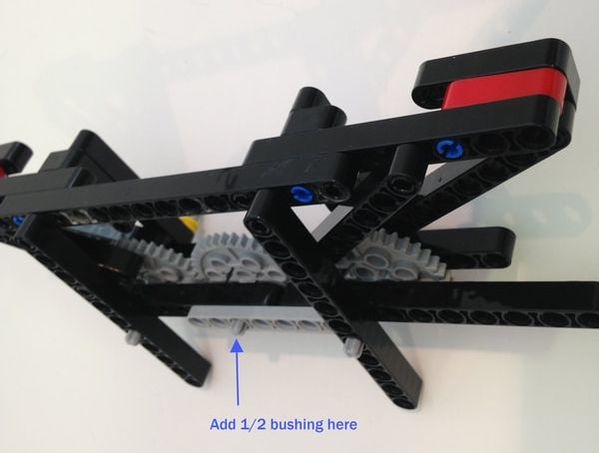
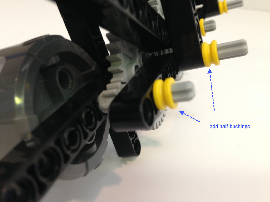
If your legs collide with the frame or cranks when rotating, then rotate the legs by hand (by turning a large gear) and look carefully at your build to see where the collisions are occurring. Perhaps you are missing some of the bushings highlighted below, or perhaps your double length crank has knobs protruding out.
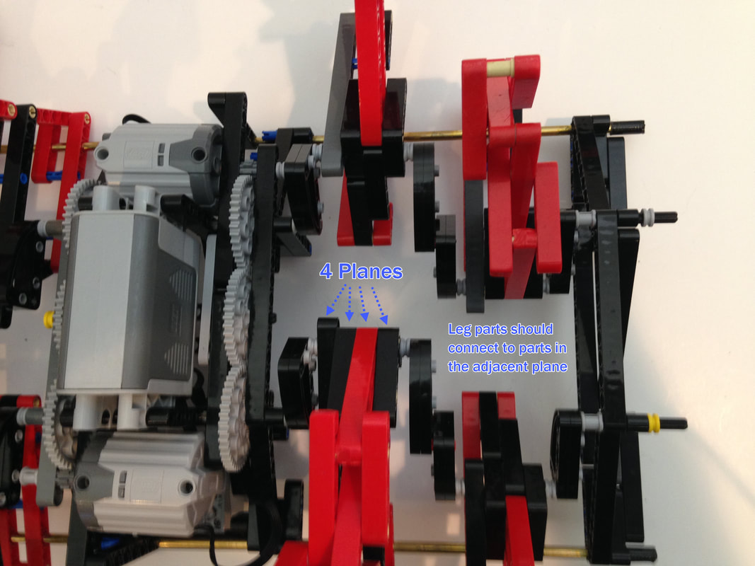
If leg parts aren't connected to parts in the adjacent plane the linkage can be twisted, which will cause the leg joints to bind. If your legs don't rotate easily, make sure your legs aren't twisted and that each part is in its correct plane as pictured below.
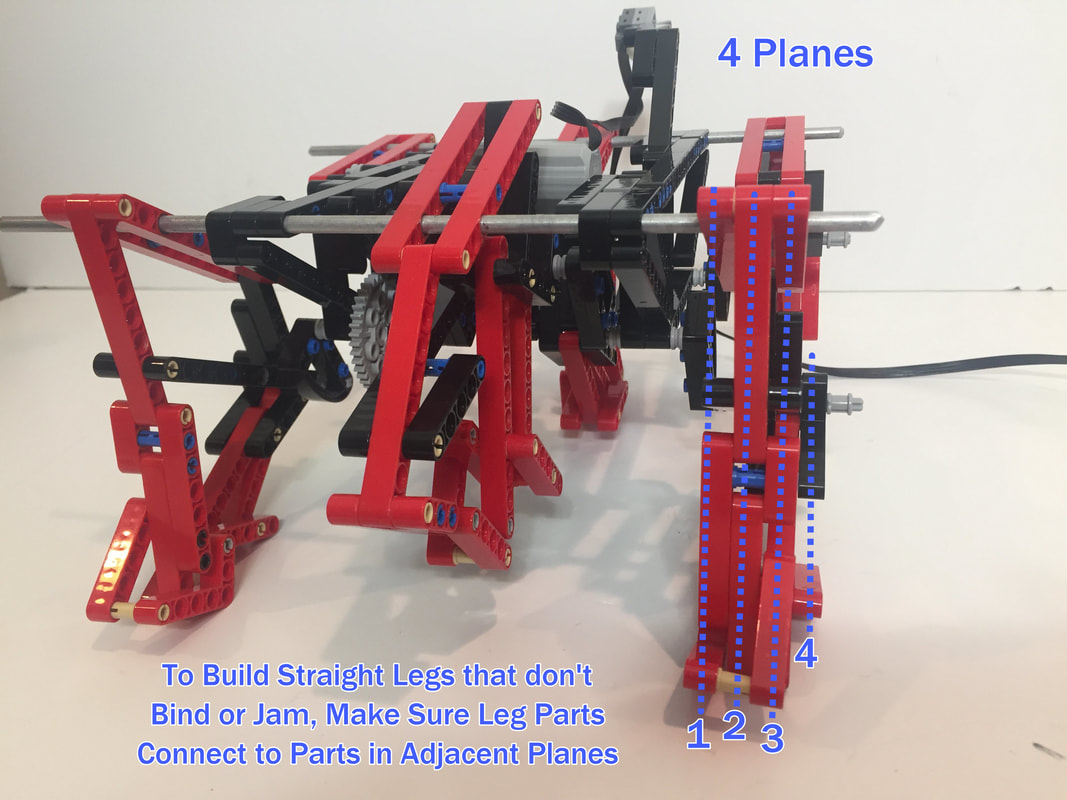
Hexapod TrotBot uses the same, 4-plane legs as TrotBot Ver 3
How to Build
General Comments:
1. Walkers stress frames more than wheeled vehicles so strive to utilize triangles that resist bending forces.
2. Be sure to use frictionless pins for movable joints!
3. Take care to space each bar properly, with the use of bushings on axles as necessary. If the leg parts collide the linkage can lock up causing gears to grind, and you will find it is much easier to get your leg spacing correct before assembling the entire walker than it is to fix the legs in a fully assembled walker!
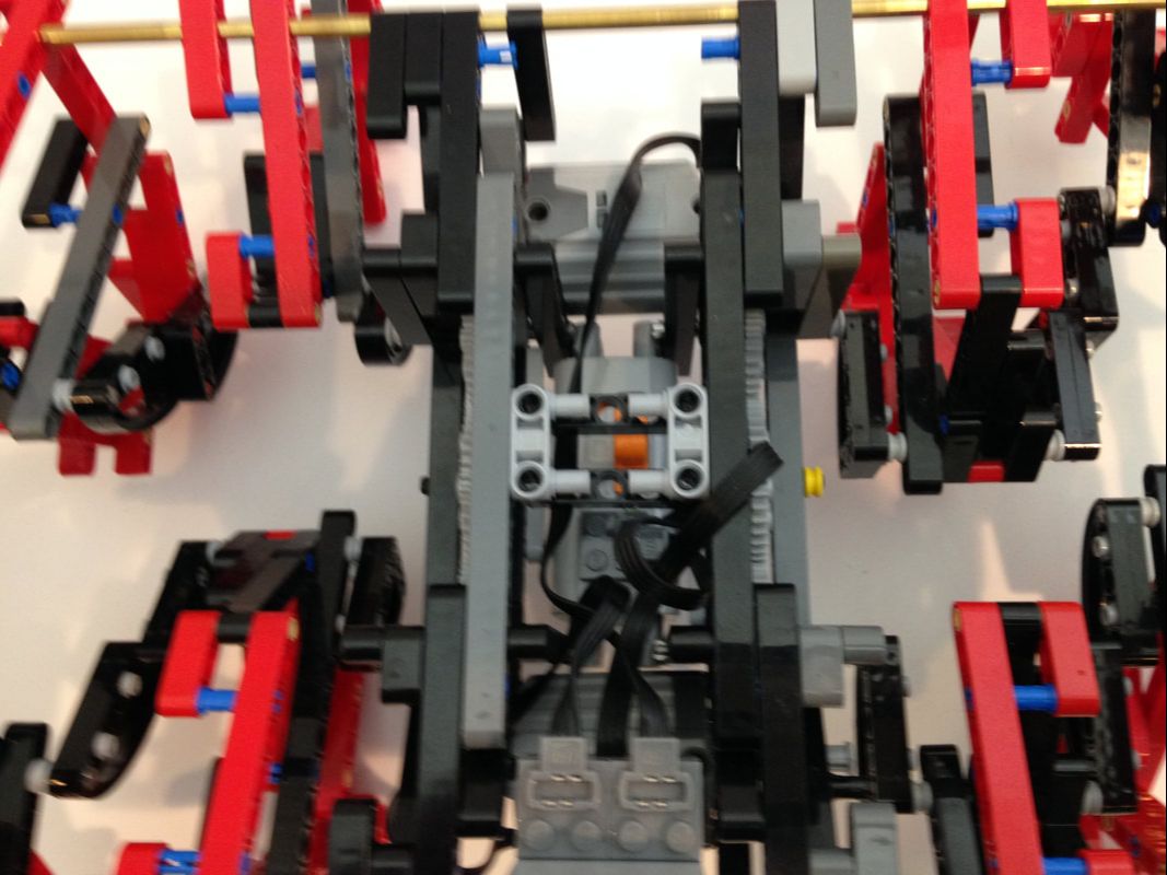
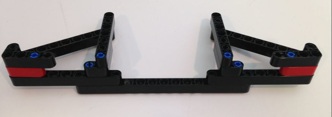
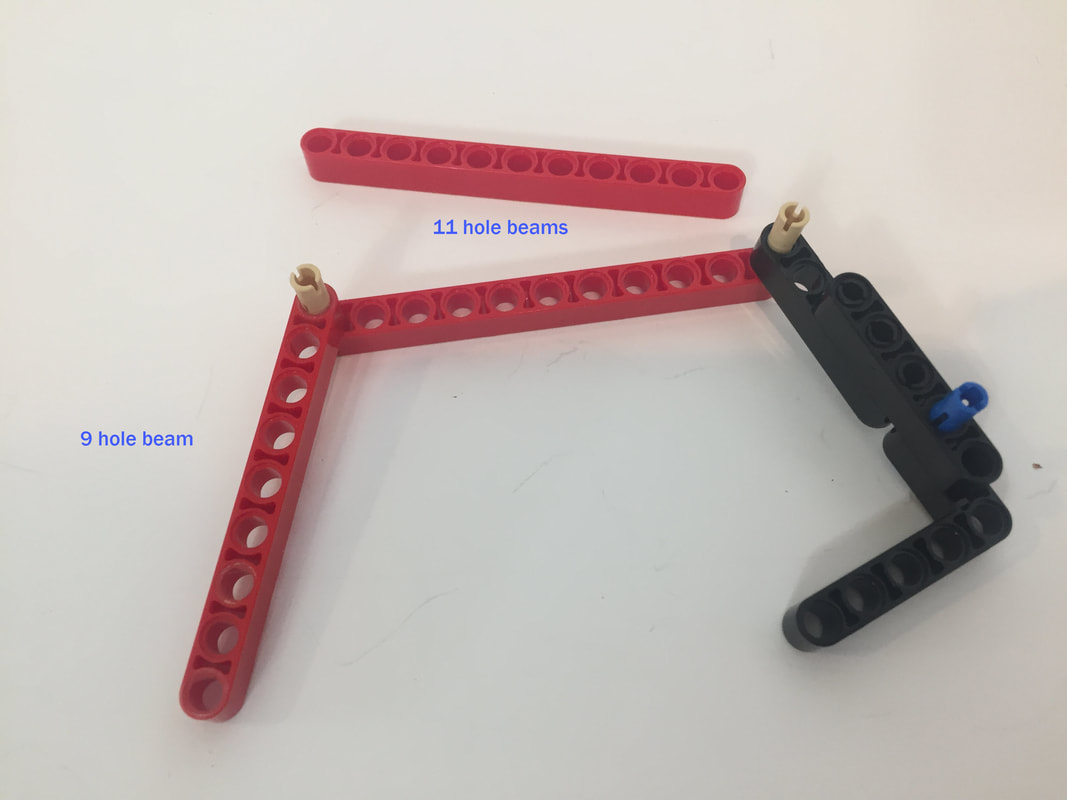
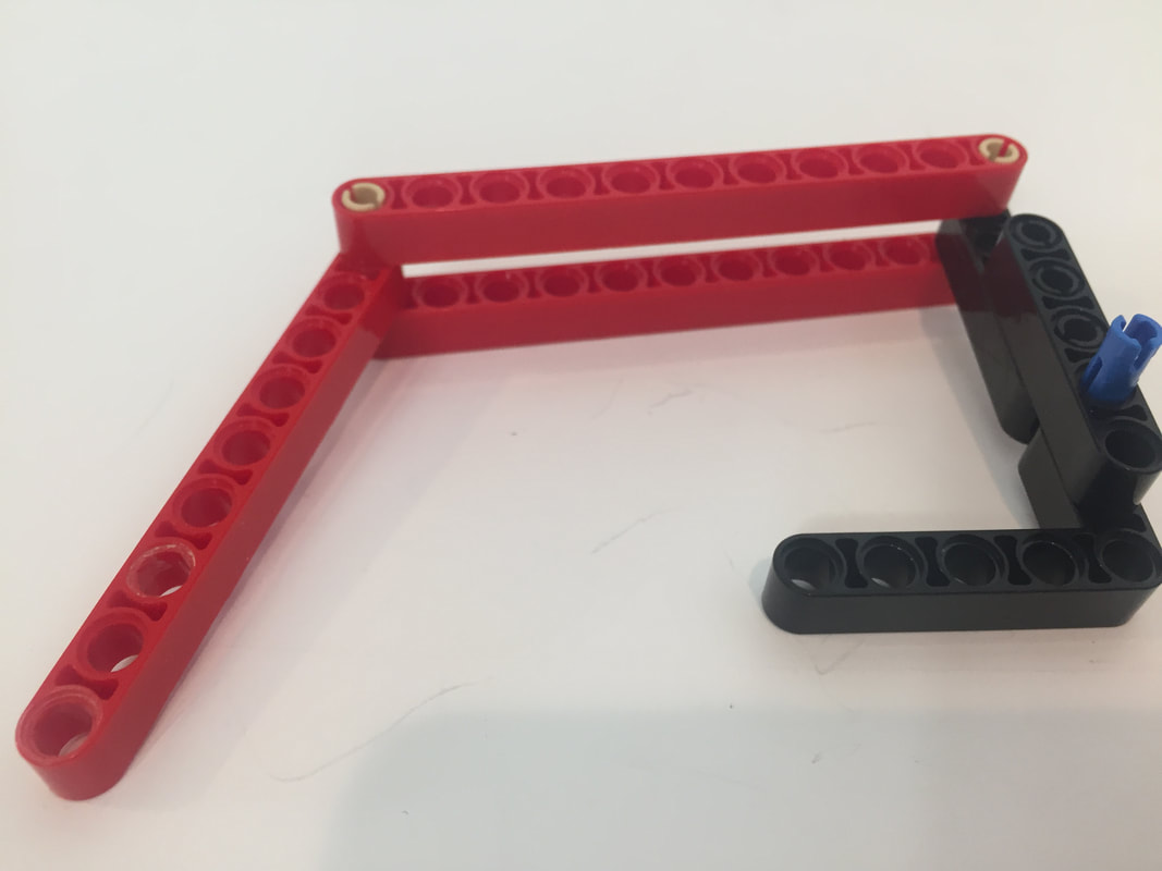
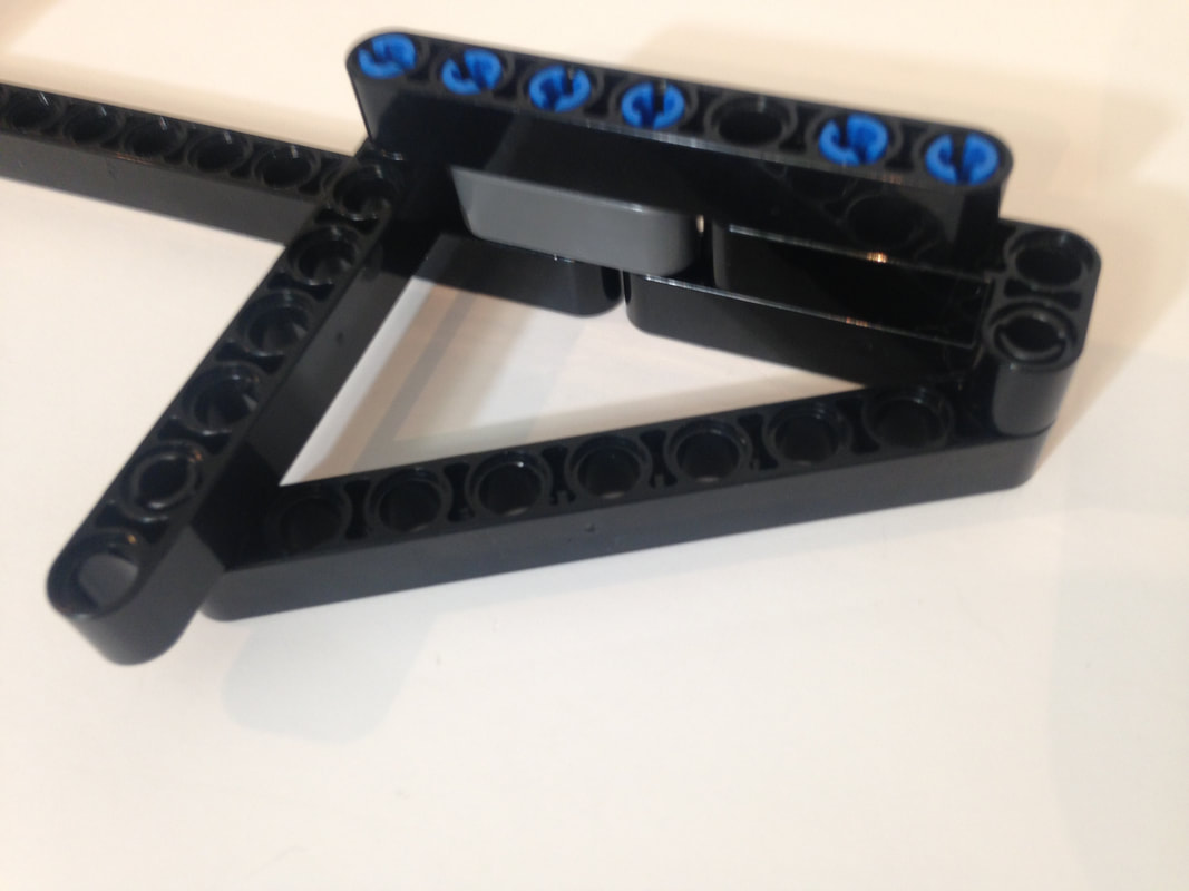
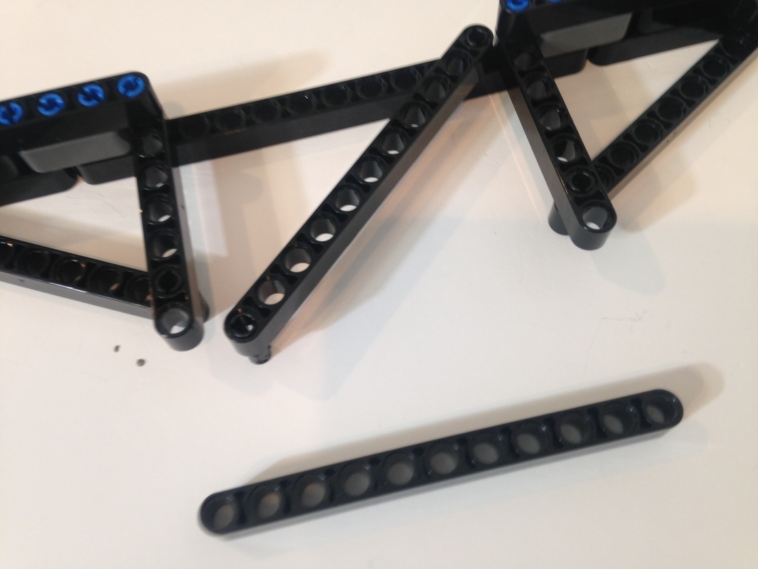
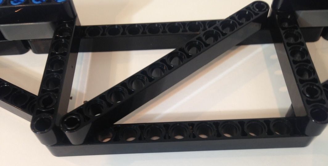
Because the battery box will be mounted on the lower section of the frame it will not provide much structural support, so we'll start by building a strong, triangle-based inner frame. You will need to make 2 of the following frames, one for each side of the robot.
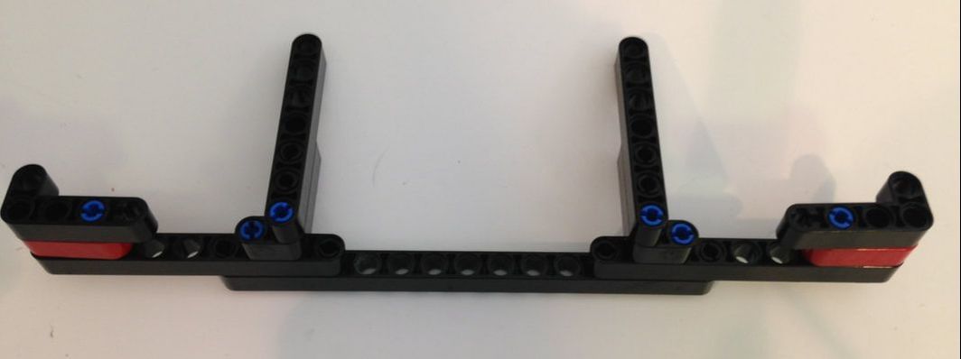
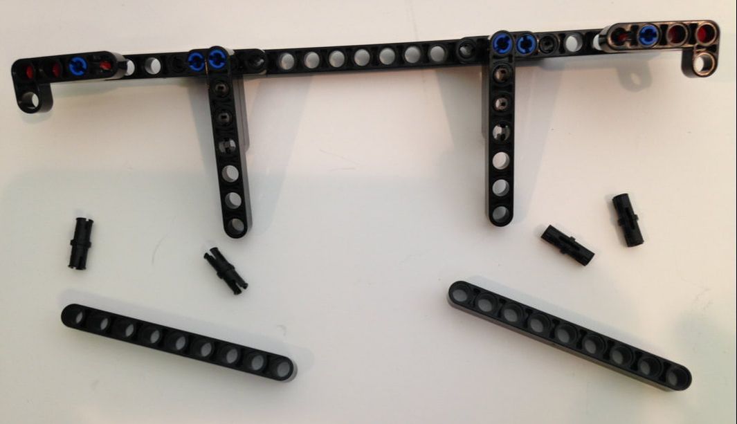
You may have noticed the 9-hole beams I used for the diagonals above are not the correct length for the triangle's hypotenuse, which I describe in this post.
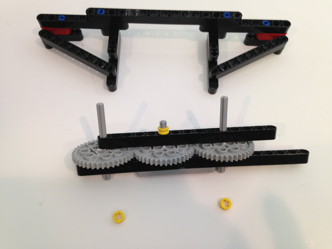
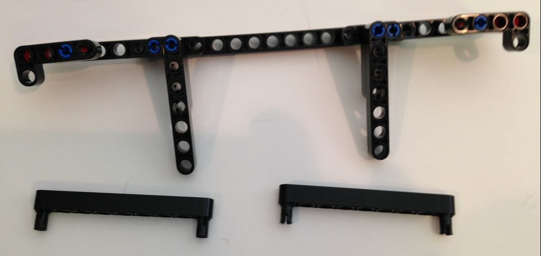
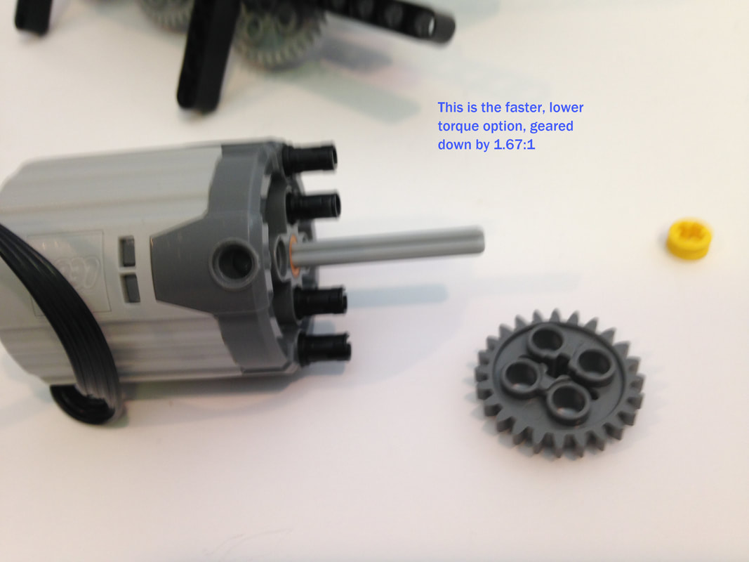
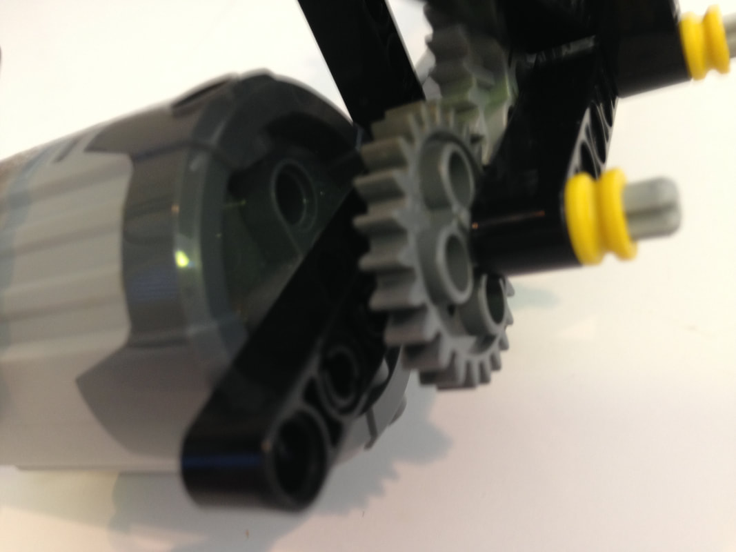
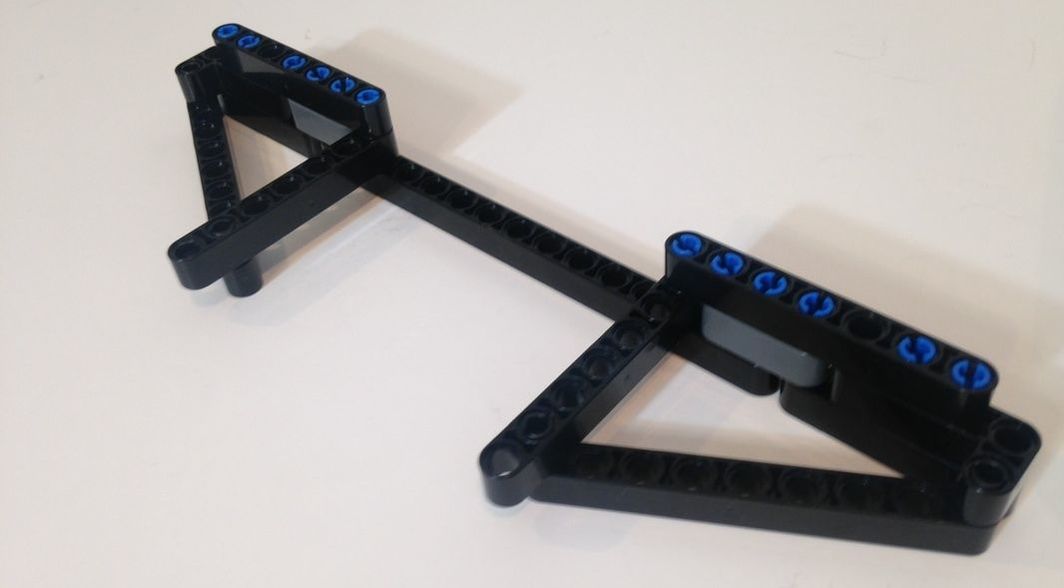
Ver 3 uses the XL motor and provides a slower speed option for climbing and higher torque use, and a faster speed option.
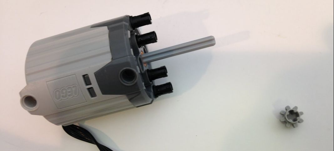
Below is the faster, lower torque option. Notice that the motor needs to be mounted 1 hole further toward the end.
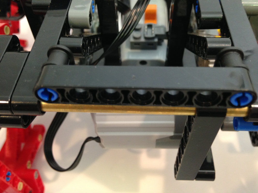
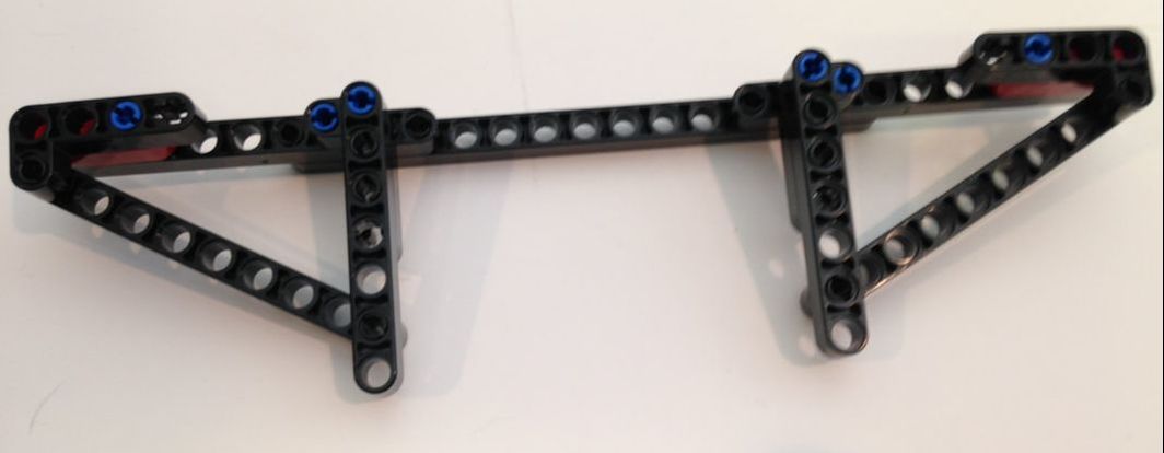
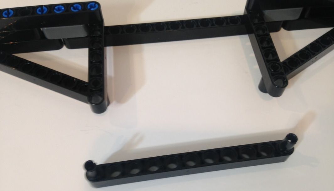
Make an identical 2nd frame as above, and then connect them with the below metal tubes.
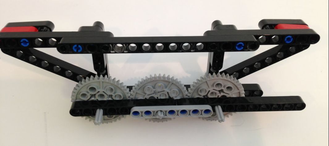
I cut the below brass tubes to 17 inches. Be sure to file down the cut so that the tubes slide easily thru the beam's holes.
I cut the below brass tubes to 17 inches. Be sure to file down the cut so that the tubes slide easily thru the beam's holes.
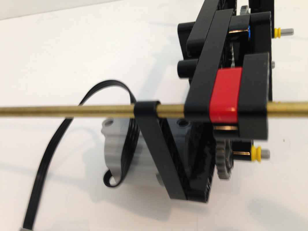
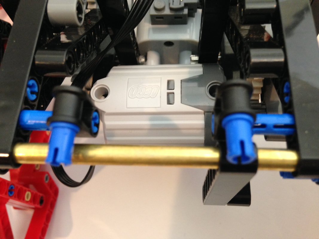
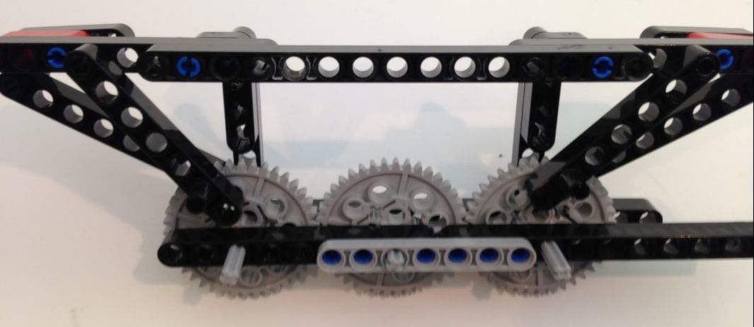
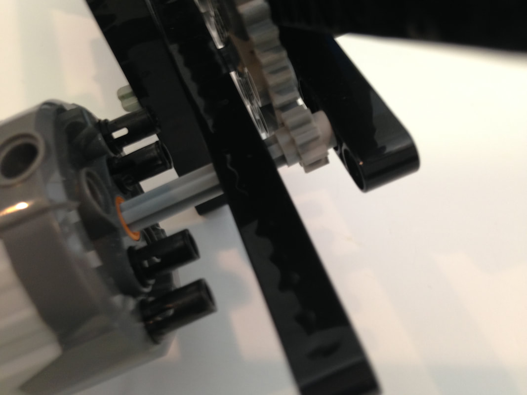
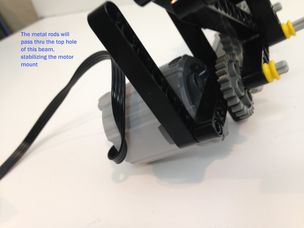
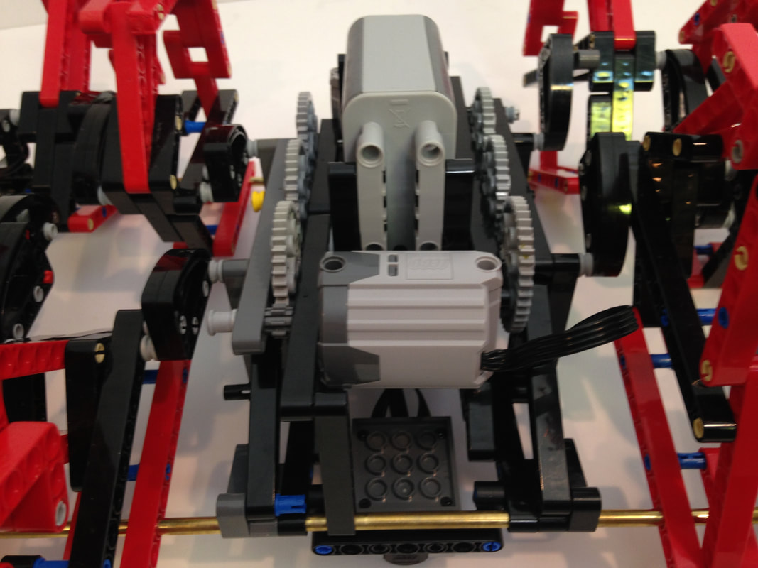
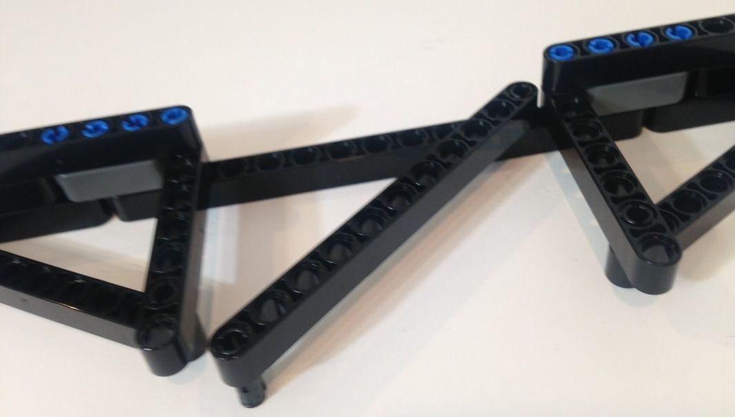
The below picture skips ahead to after the legs have been added, but I included it to show the brass tubes connecting both sides of the frame. Instructions for building the legs are further down in these instructions.
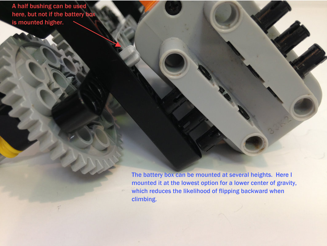
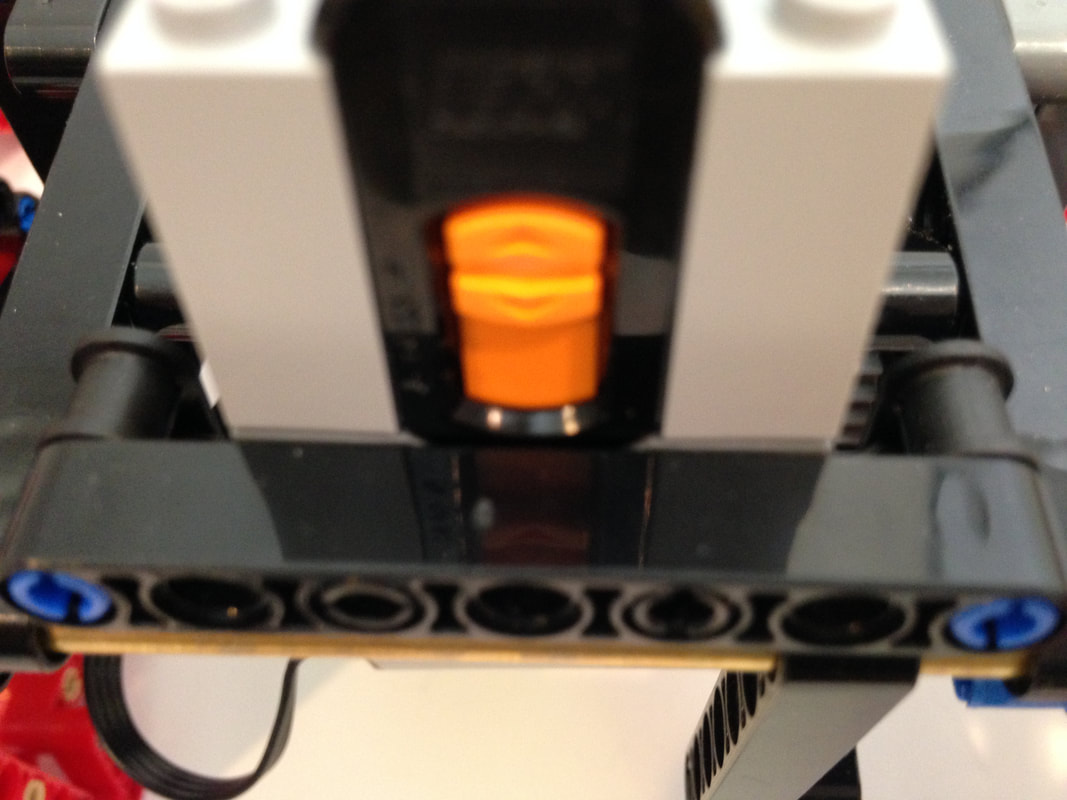
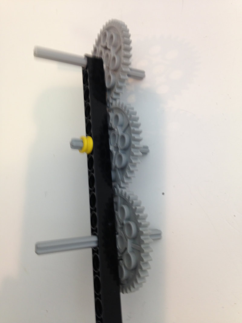
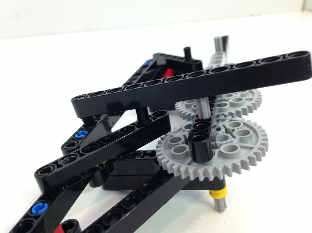
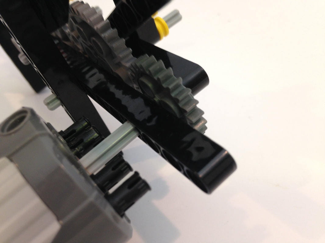
Notice I did not put a bushing on the inside of the gear's axle above. If the battery box is mounted low like above then a bushing can be added to sandwich the gear train more securely, but if the battery box is mounted higher it can't.
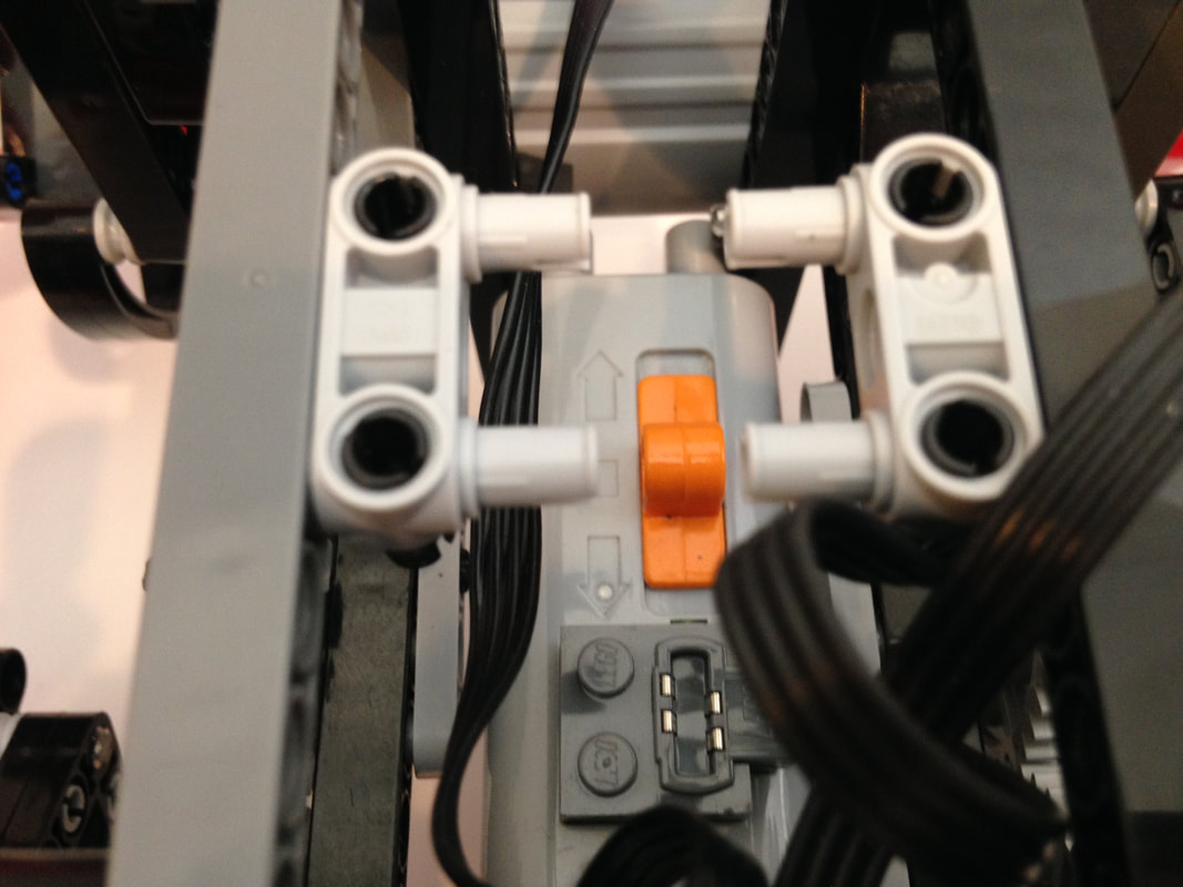
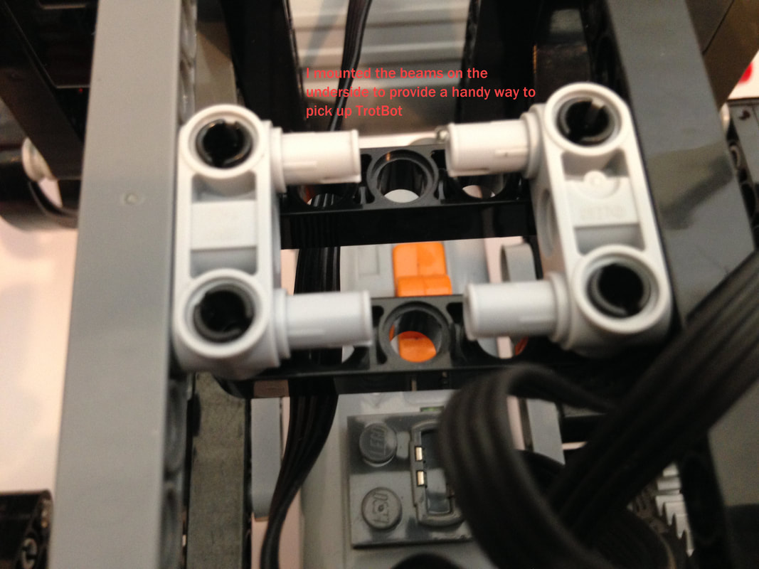
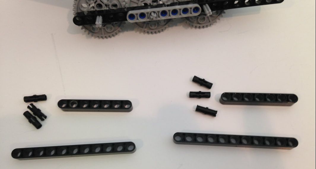
I mounted the 5 hole crossing beams on the underside to provide a handy way to pick up TrotBot.
Legs and Cranks
|
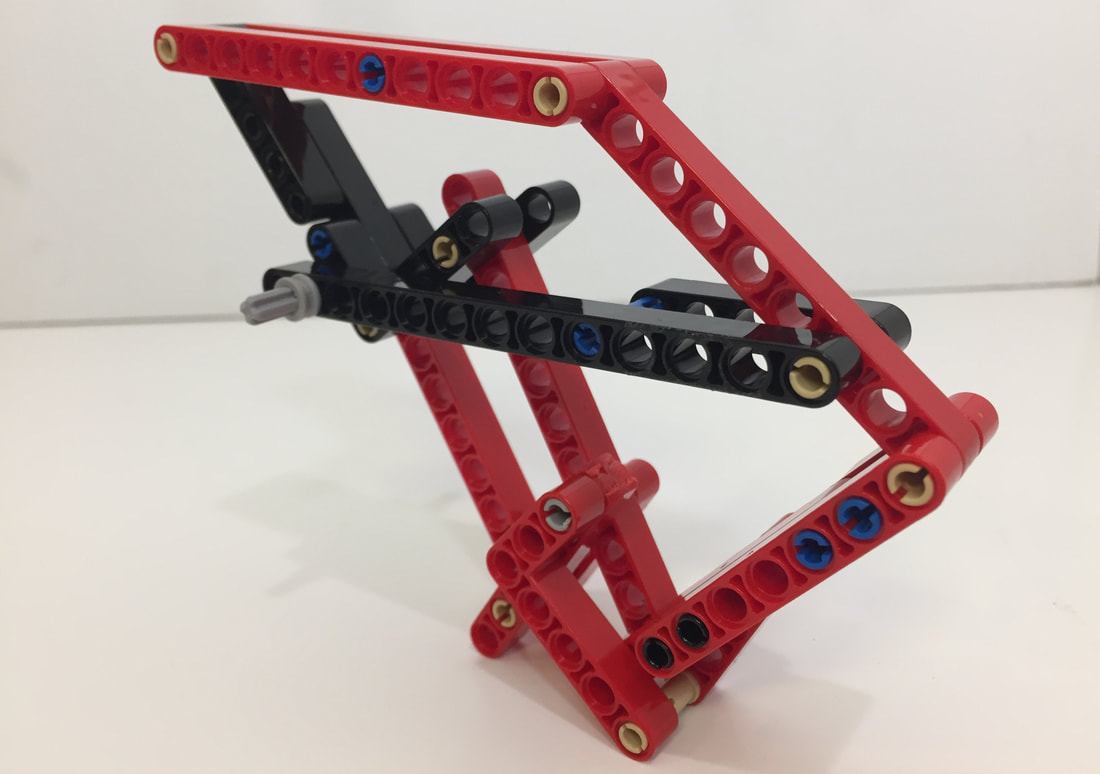
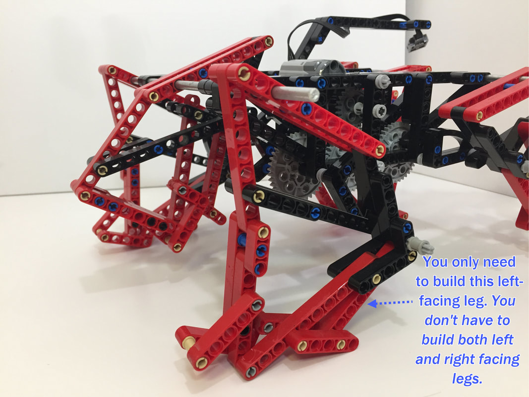
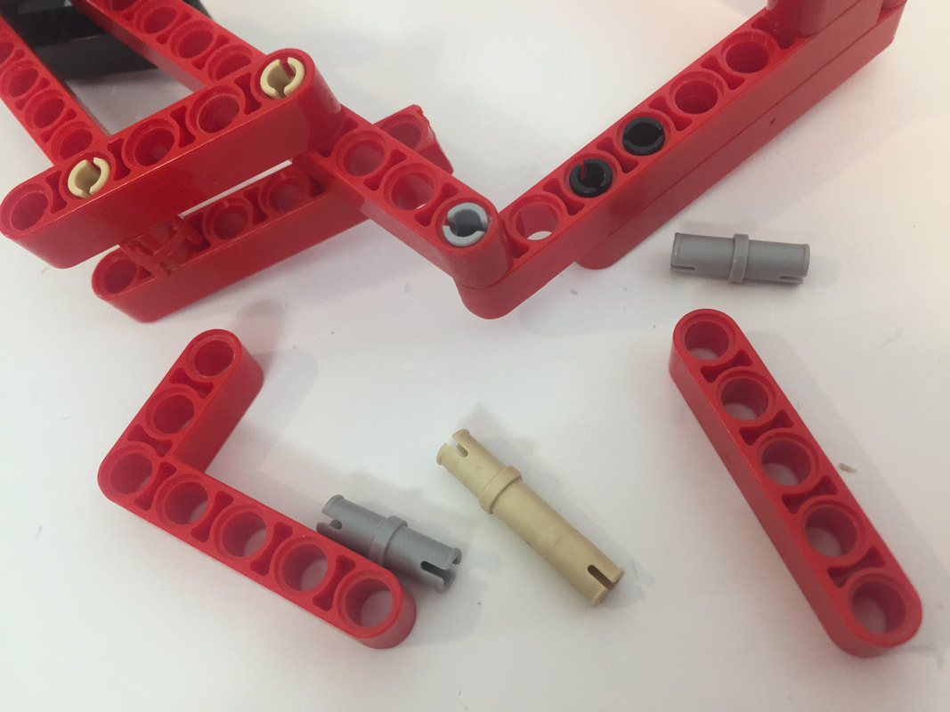
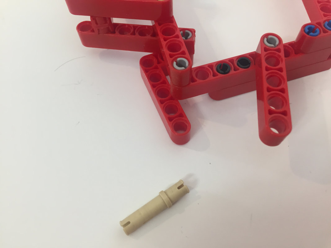
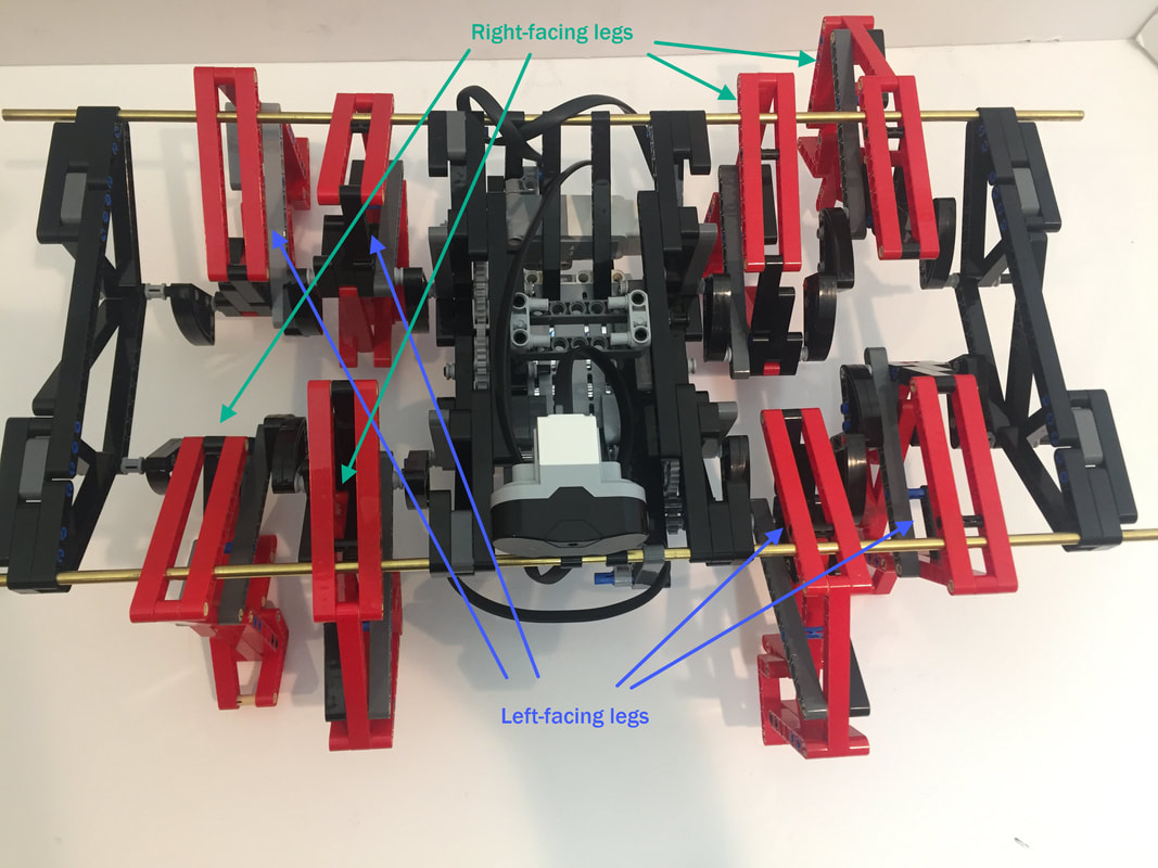
Below I show how I built the stronger version of TrotBot's legs, where the joints are sandwiched between two beams, allowing the legs to better handle sideways forces without the pins coming out. Update: The following instructions have 4 of the legs built in a left-facing orientation, and 4 in a right-facing orientation, but you can build all 8 legs in either orientation since it won't affect TrotBot's functionality. Here are some simplified instructions for building TrotBot's leg mechanism. This leg will work for all 8 legs of TrotBot. Alternatively, instructions for building both left and right-facing legs are below. |
Simplified Instructions for Building TrotBot's Leg Mechanism
|
Hexapod TrotBot
I'll build the left-facing leg first. Make 4 of the following legs.
NOTE #1: My finished build doesn't have a 2nd 11 hole beam like above - rather than take it apart I simple added a 3 hole beam to sandwich the top right joint.
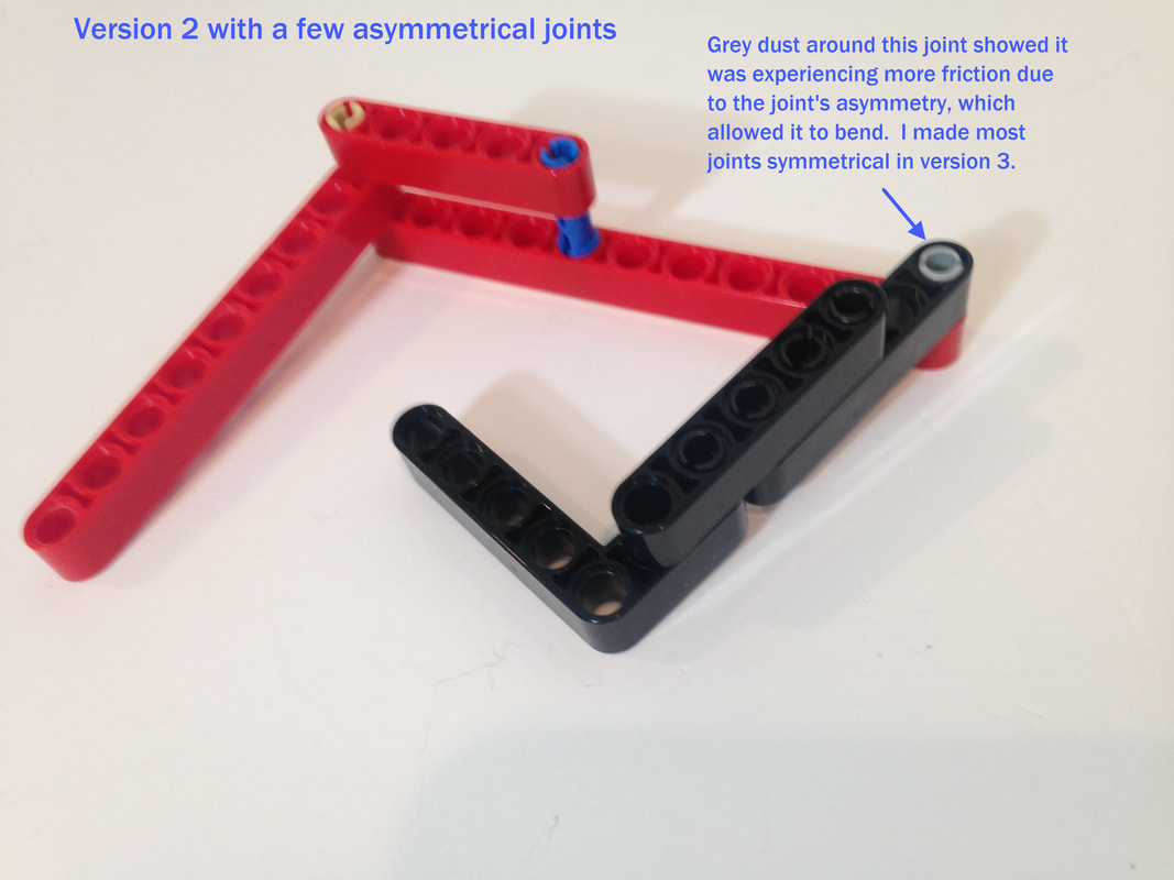
NOTE #2: The reason I added a second 11-hole beam to the top of the legs (above) is the previous, single beam versions allowed the top right joint to bend somewhat, and the joint was starting to wear. Below is a picture of this previous version. Grey dust had accumulated around the joint, indicating the frictionless pin was being worn , so rather than be cheap with parts I decided to build TrotBot properly with symmetrical joints.
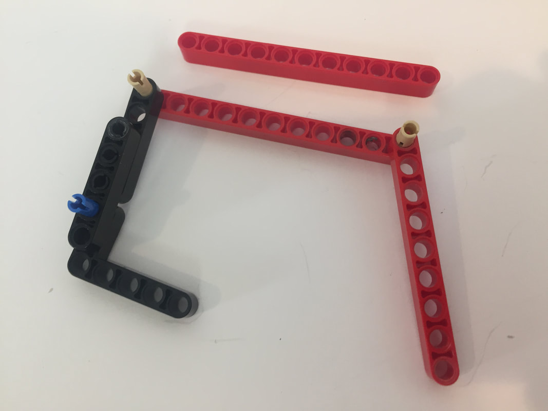
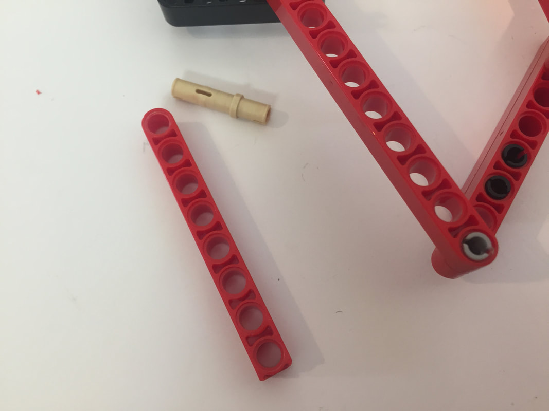
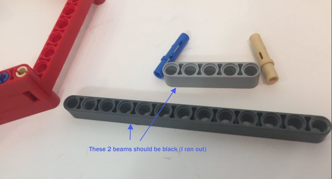
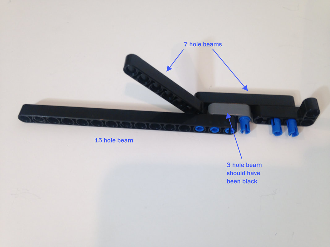
Next, I add the front side of the lower leg, which I created with 3 beams to accommodate the retractable toe's linkage (added later). If you don't want to use toes then you can still build the foreleg like below, or build them like TrotBot ver 1's.
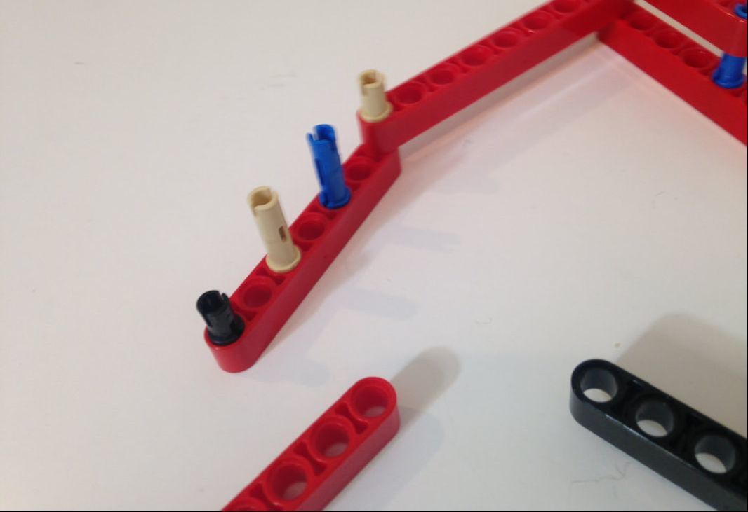

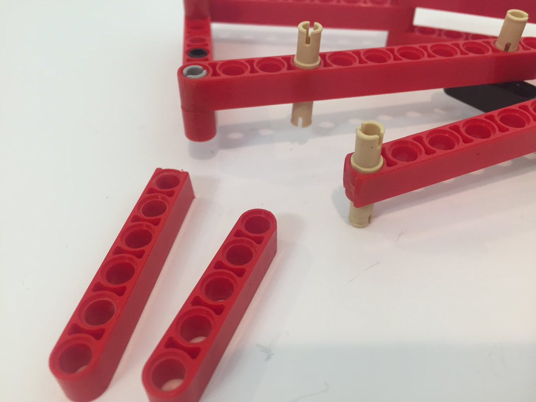
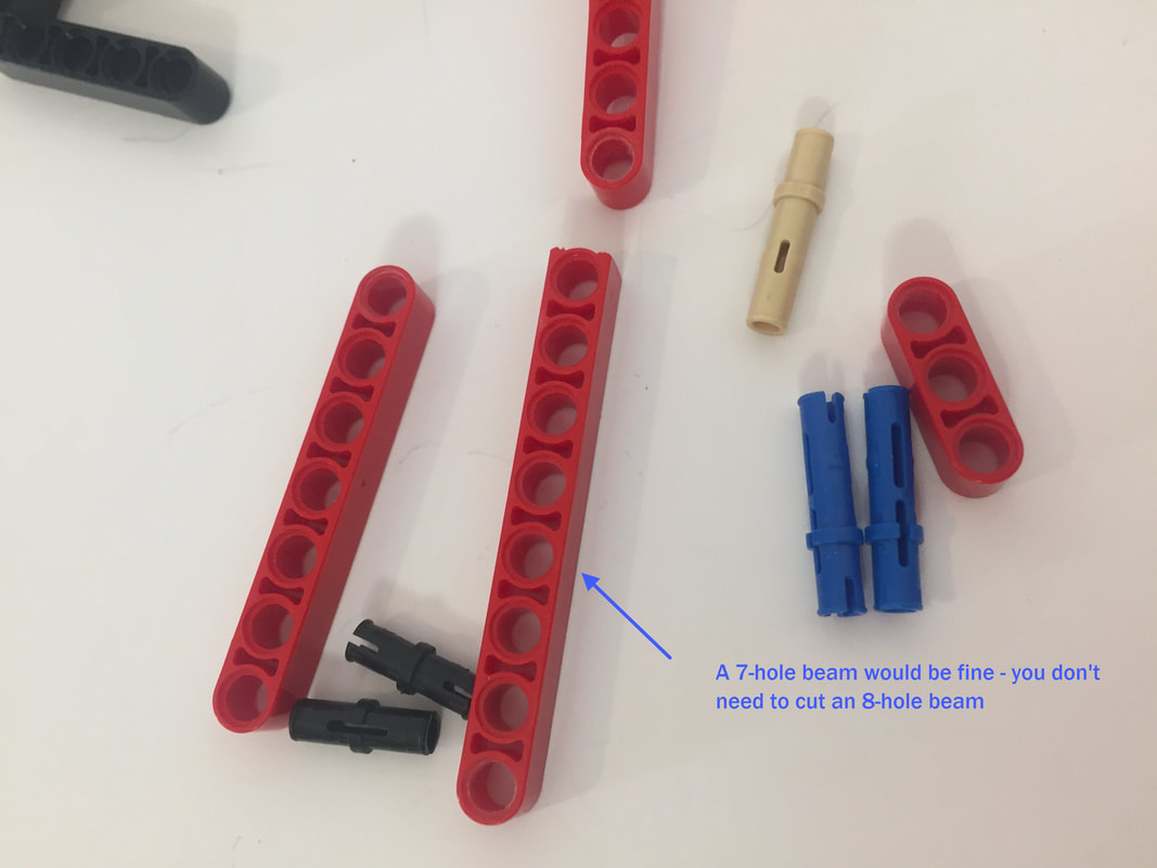
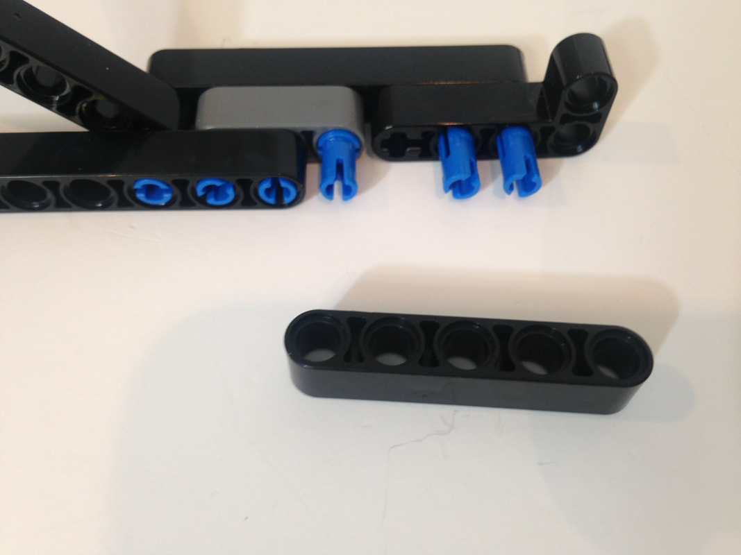
NOTE: Previously I had used a hobby saw to make some 8-hole beams, and used these spare 8 hole beams in the remaining pictures of the above leg section. However, you don't need to cut beams to create the below 8-hole beam version of this leg section - the above version works fine with two 7- hole beams and one 3-hole beam. Sorry, I didn't catch this until after I uploaded the pictures.
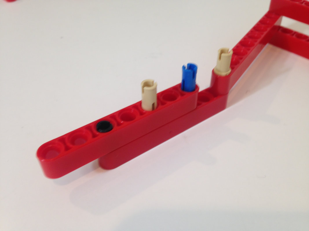
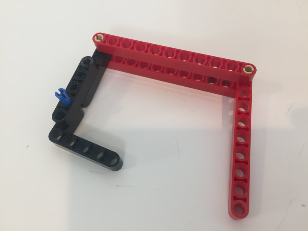
To be clear, below is the same leg section as above, but uses an 8-hole beam in the center.
To be clear, below is the same leg section as above, but uses an 8-hole beam in the center.
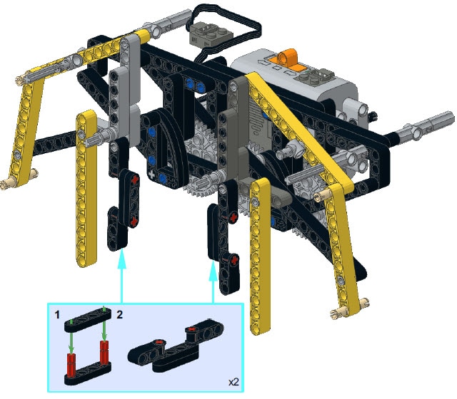
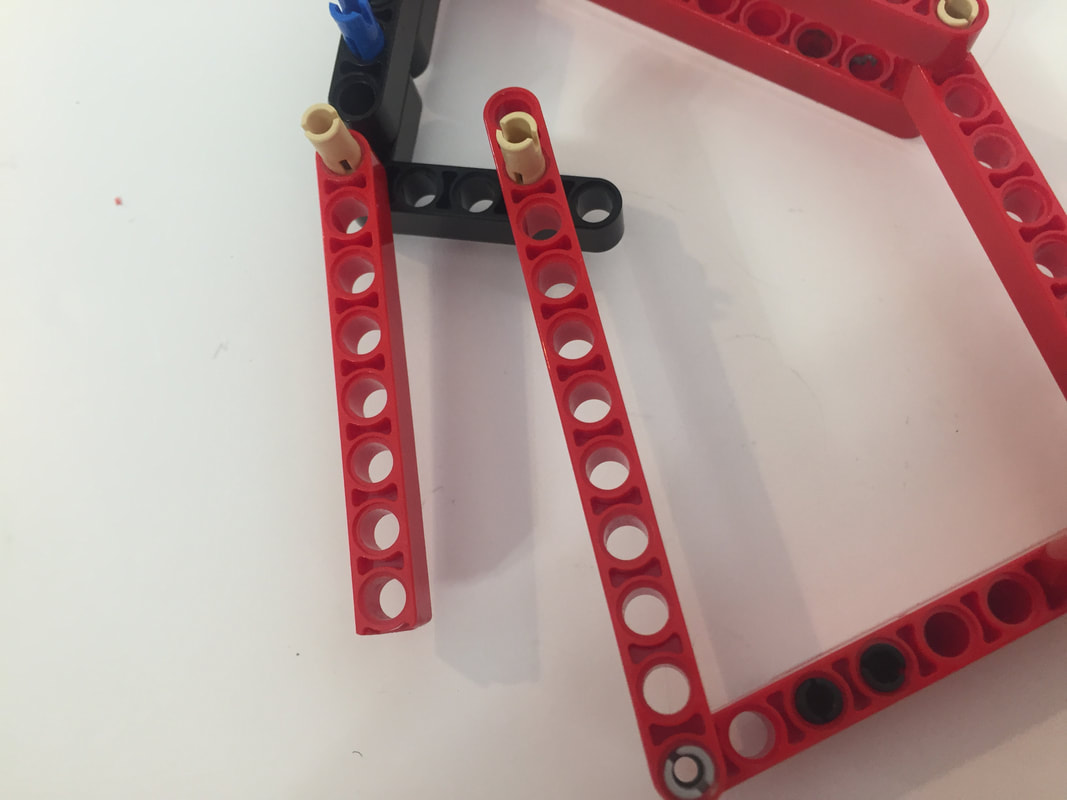
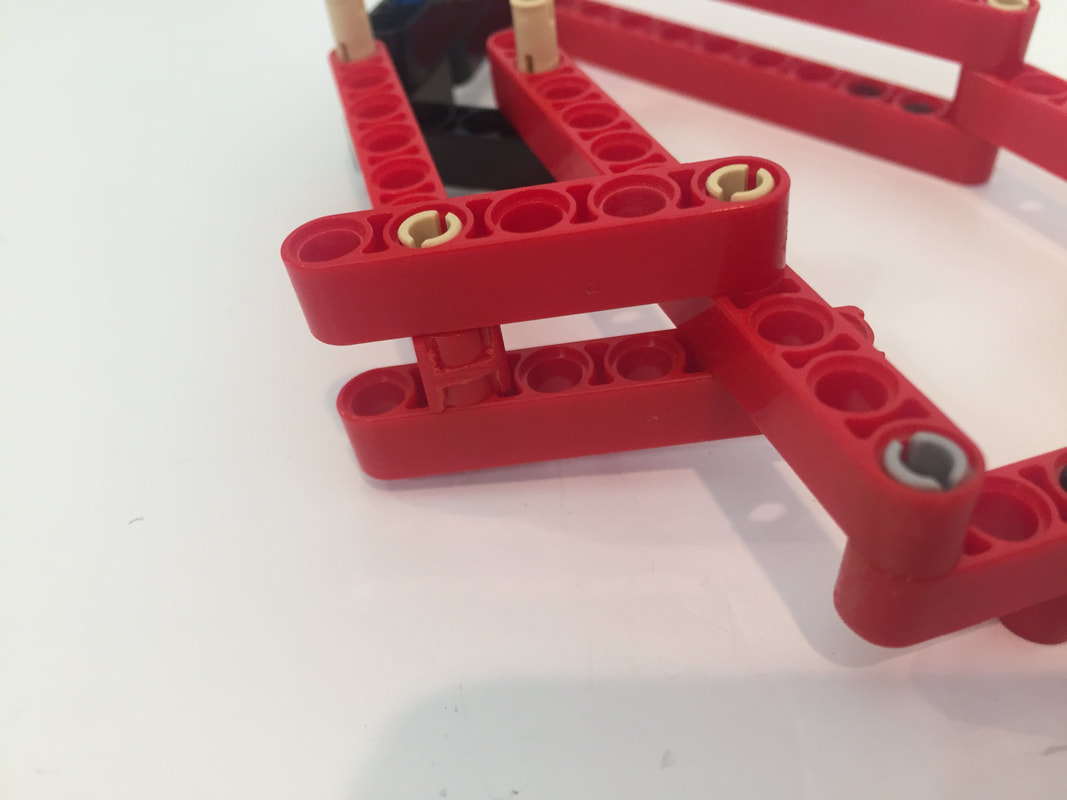
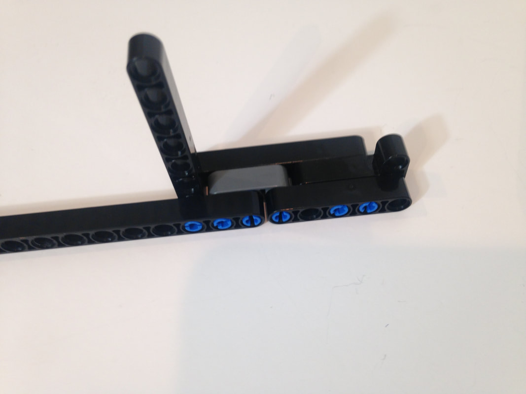
Next, I add the back portion of the lower leg as well as the beam for the heel's linkage.
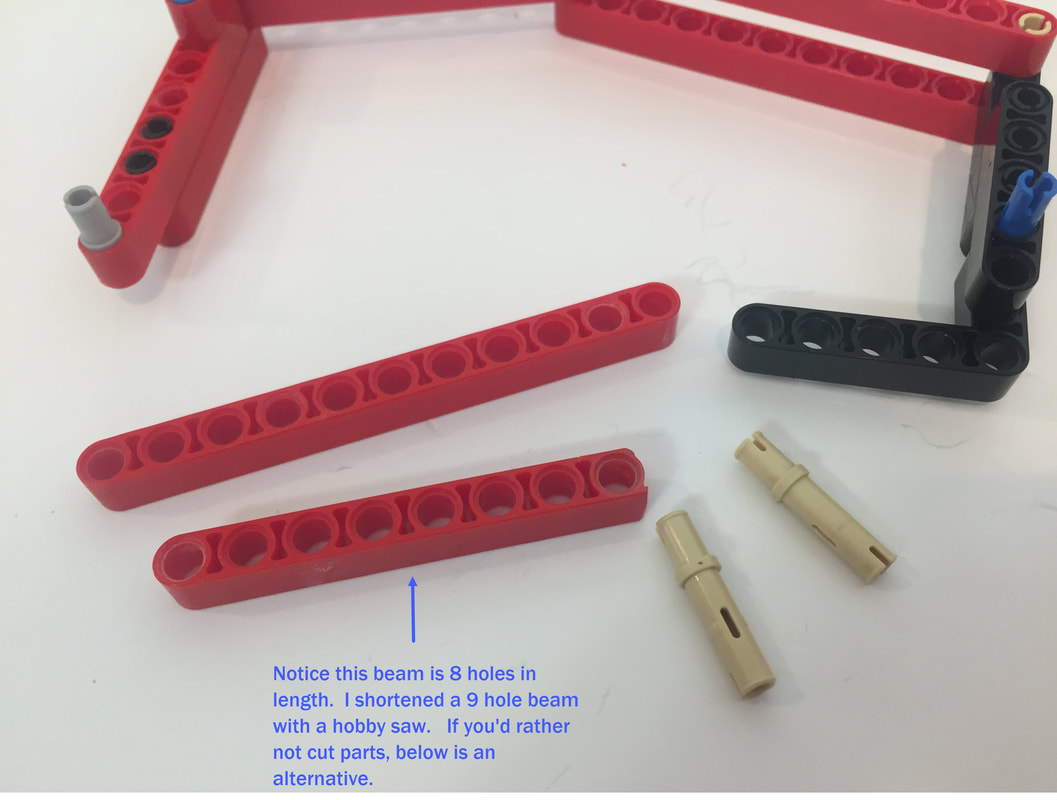
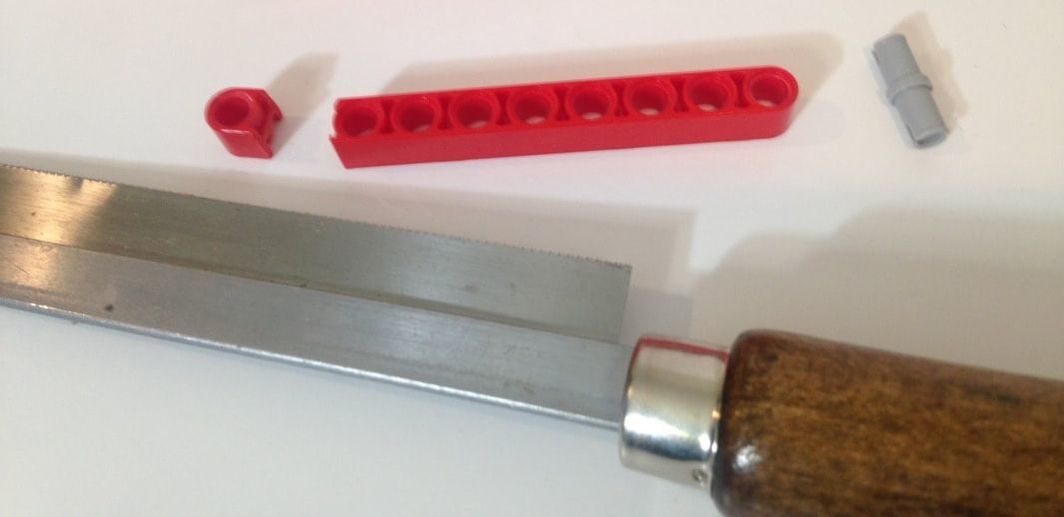
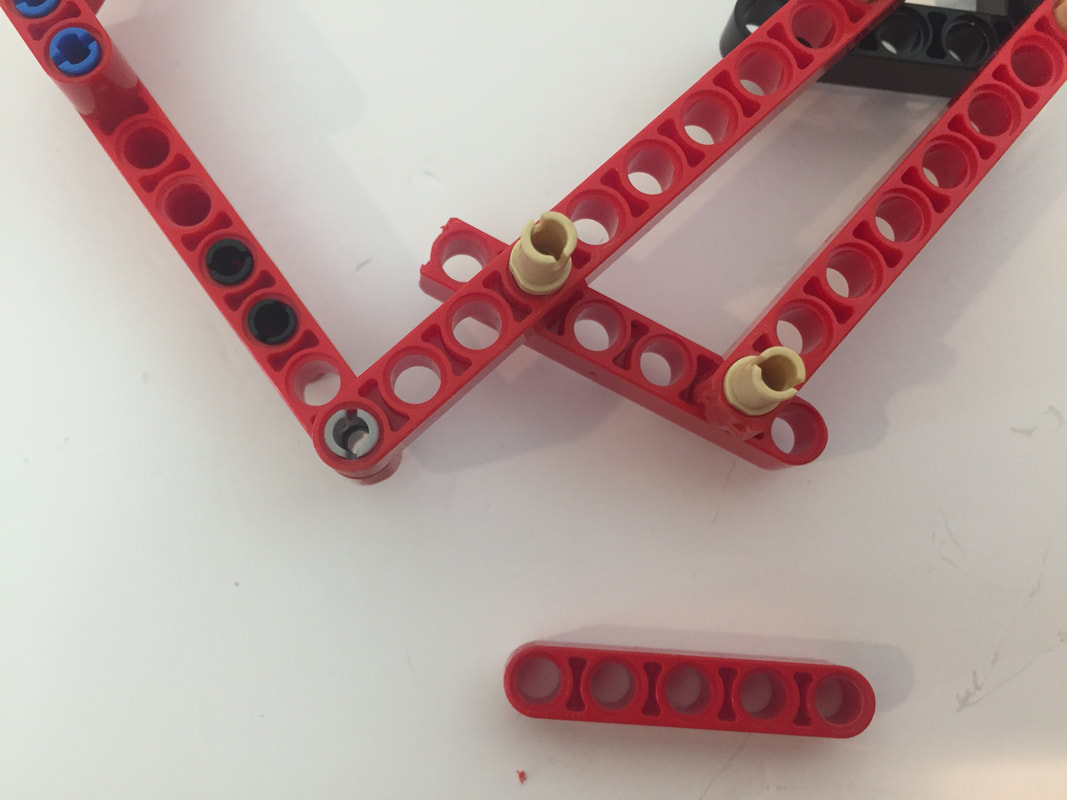
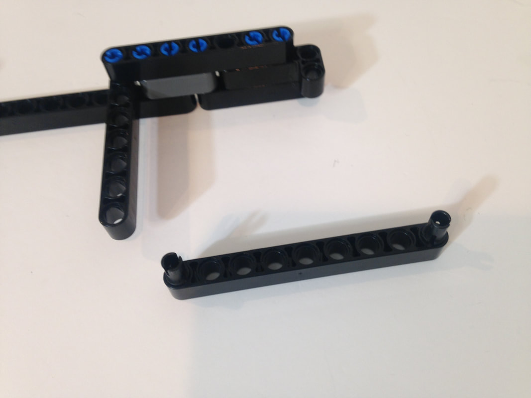
Above is the saw I used, but if you don't want to cut LEGO beams to create 8-hole versions for the heel then below is Catweazel's solution for the heel's 8 hole beam:
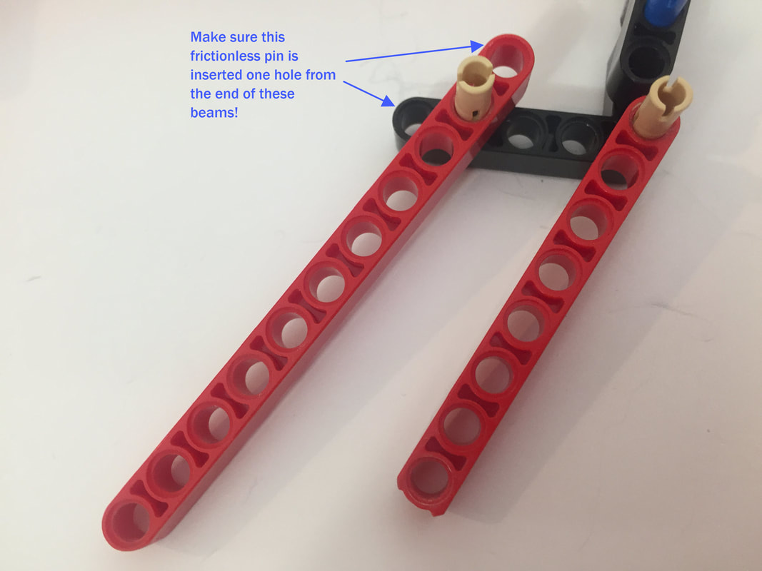
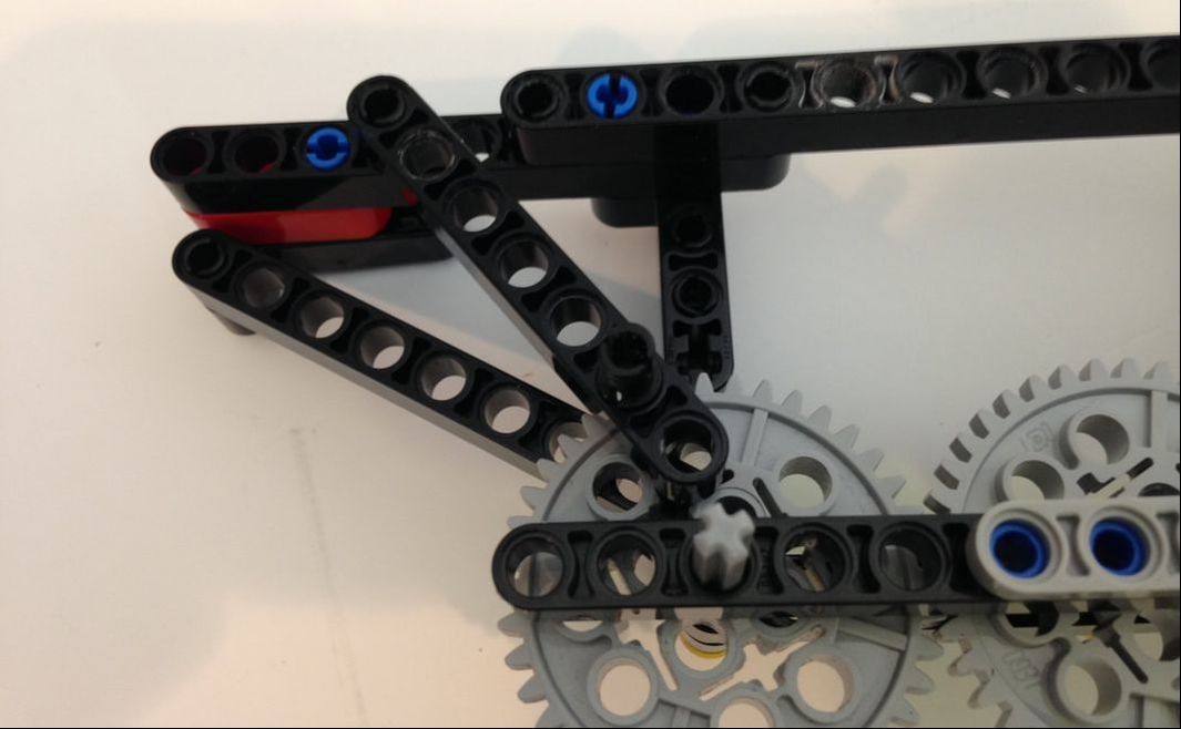
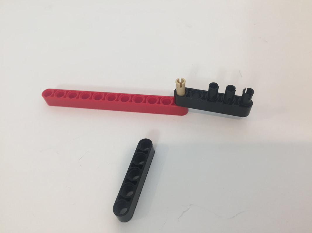
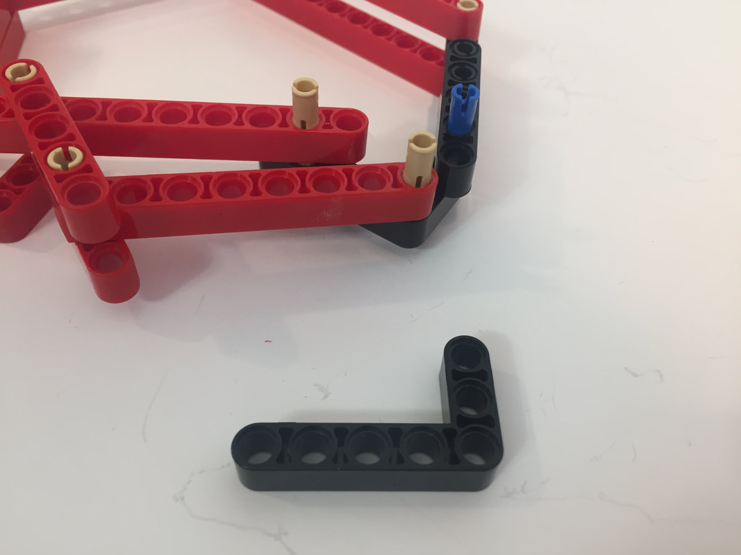
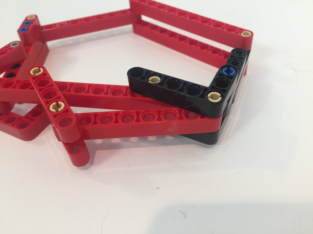
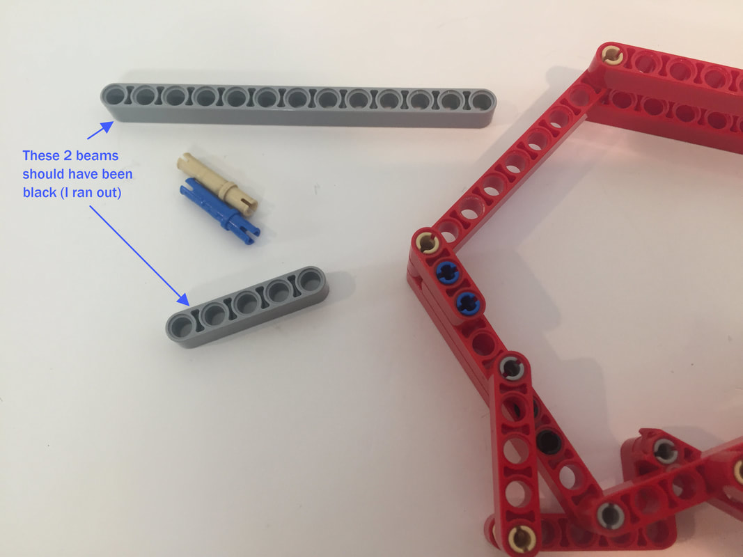
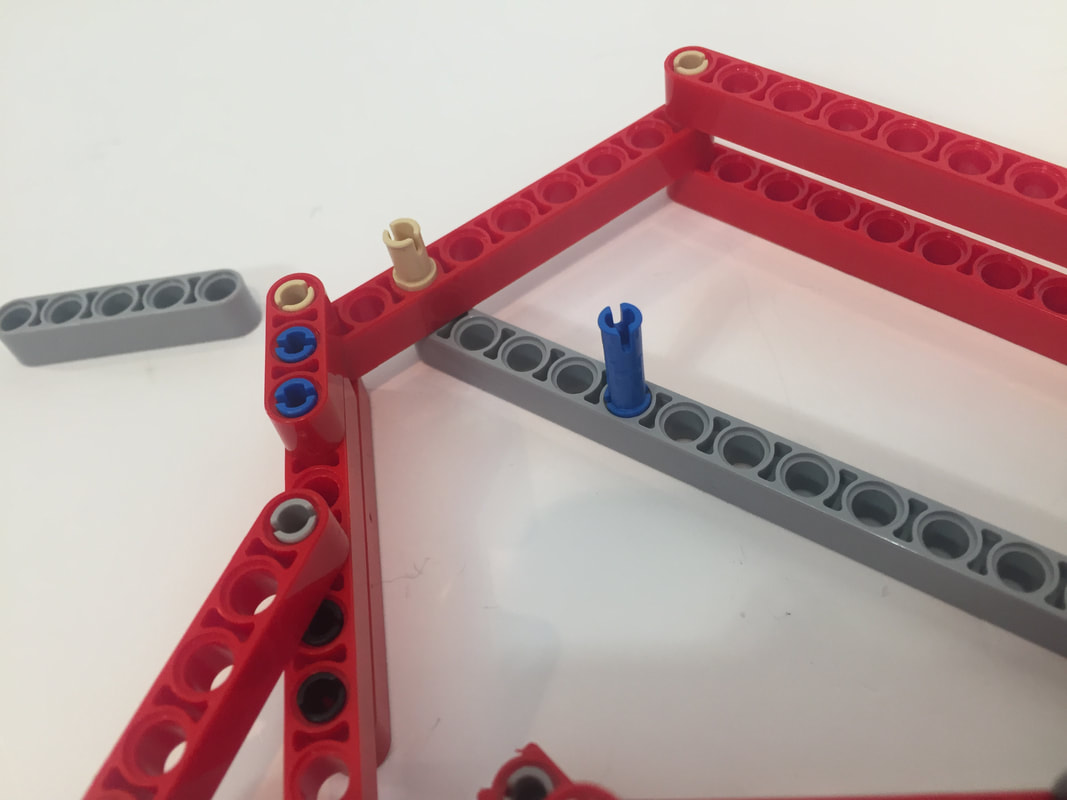
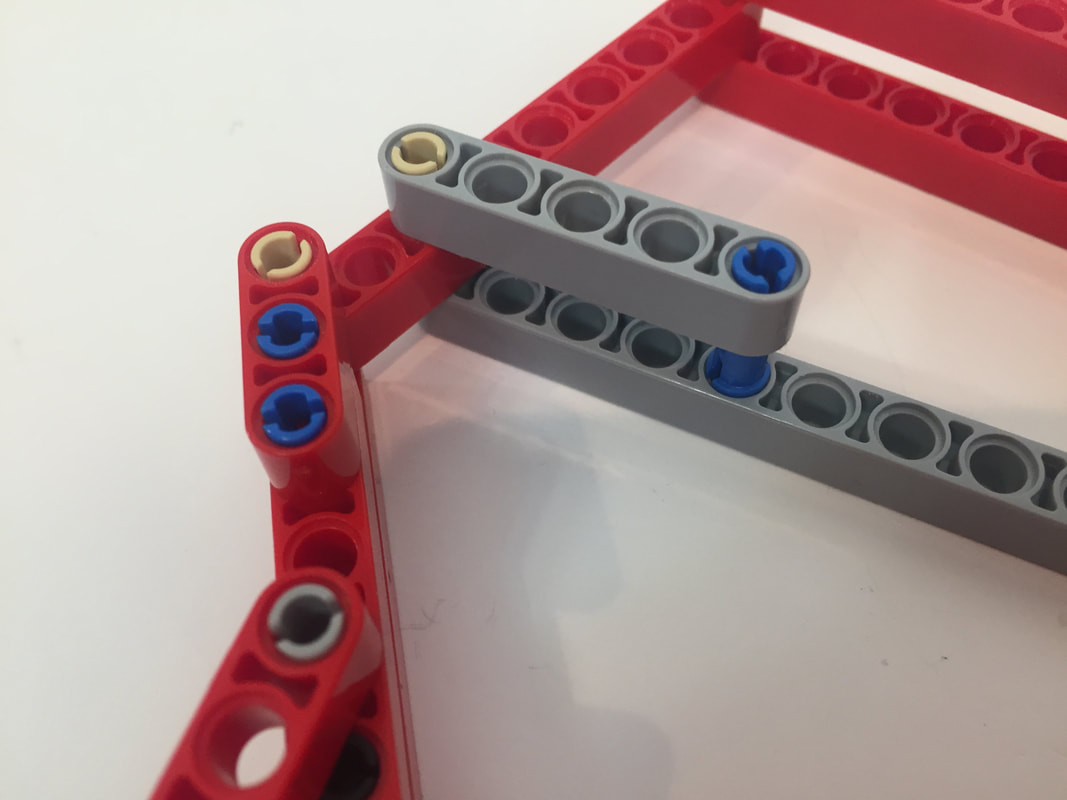
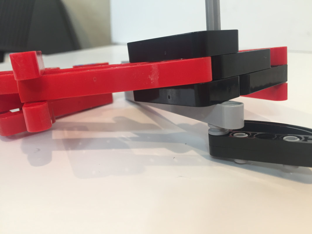
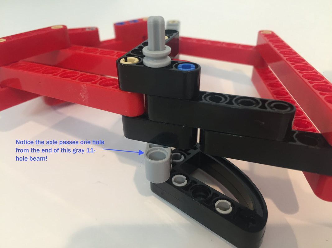
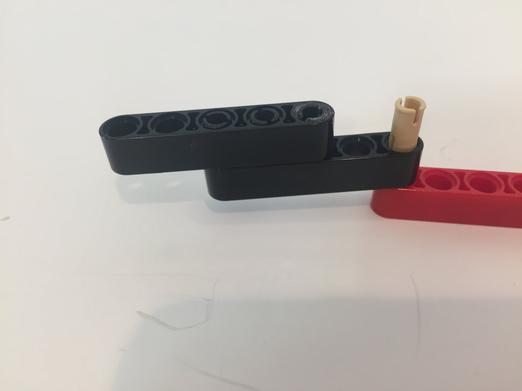
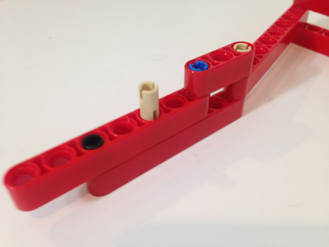
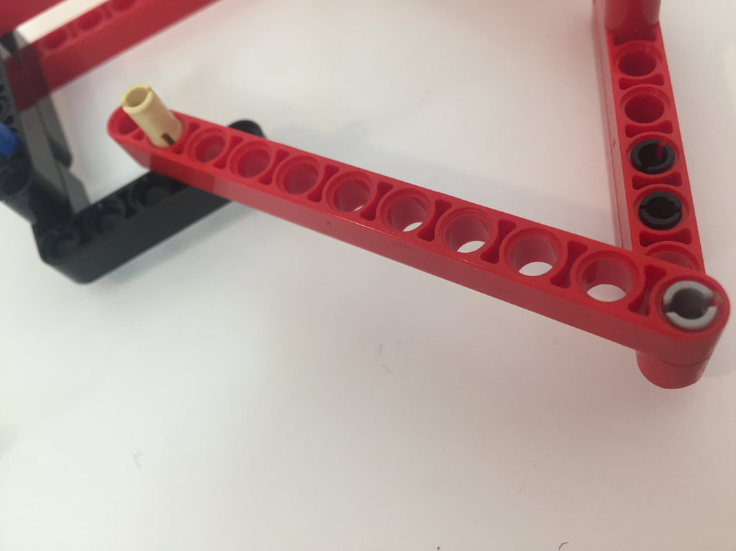
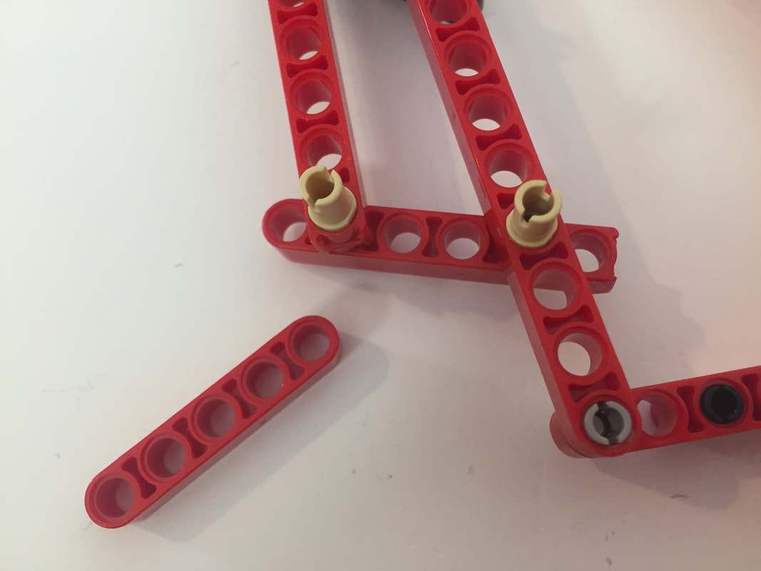
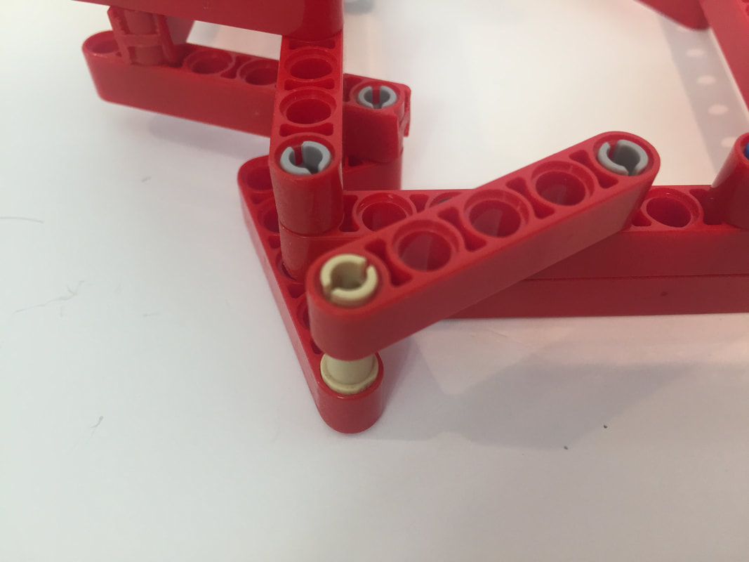
Notice the above 11 hole red beam is not attached to the end of the black 3x5 L-shaped part. Instead, the red beam is attached one hole from the end of the black 3x5 L-shaped part!
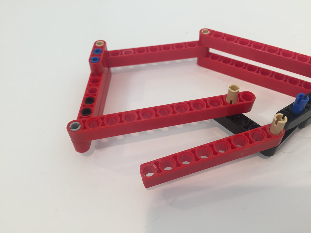
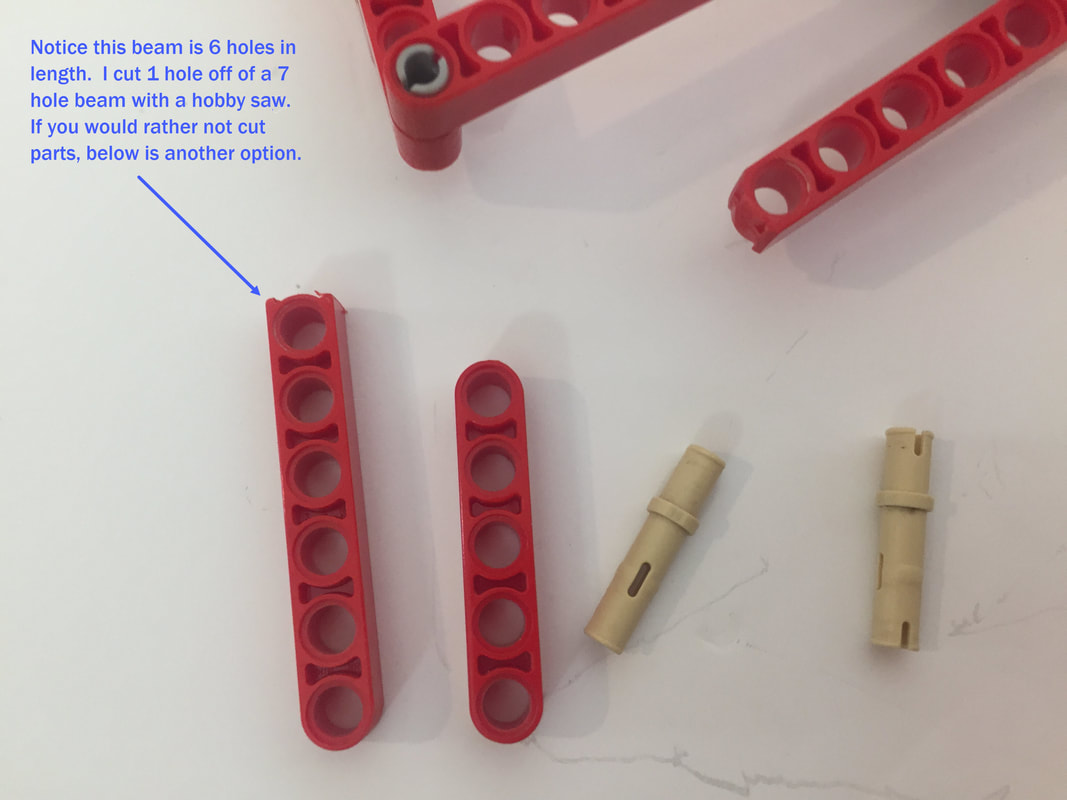
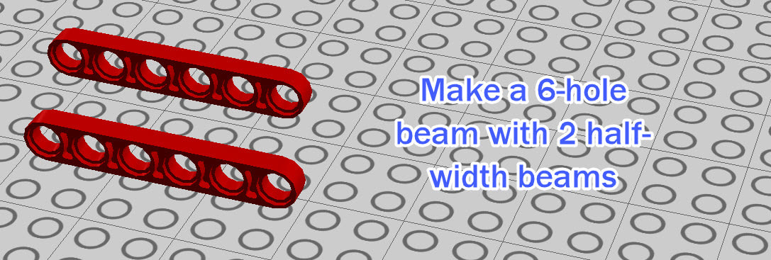
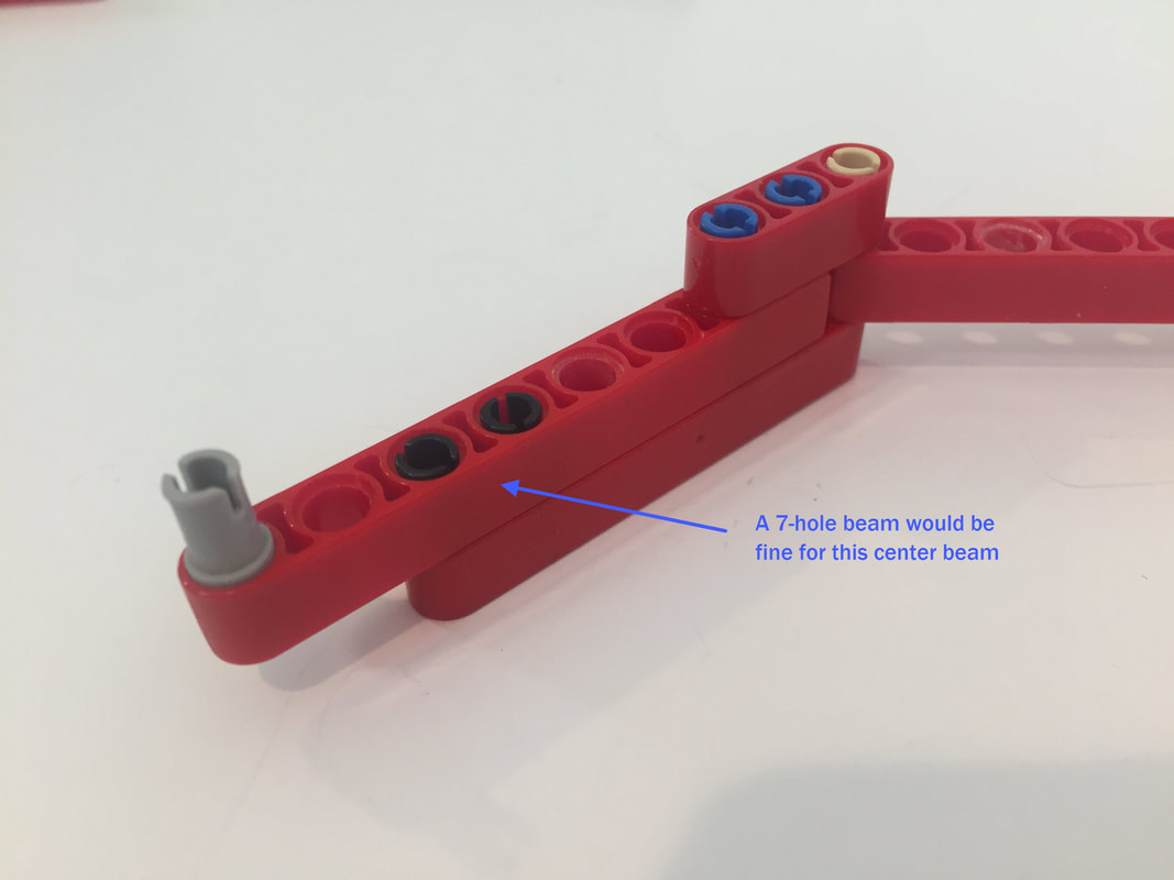
If you don't want to shorten a 7-hole beam, here's another option
Next, I add the retractable toe
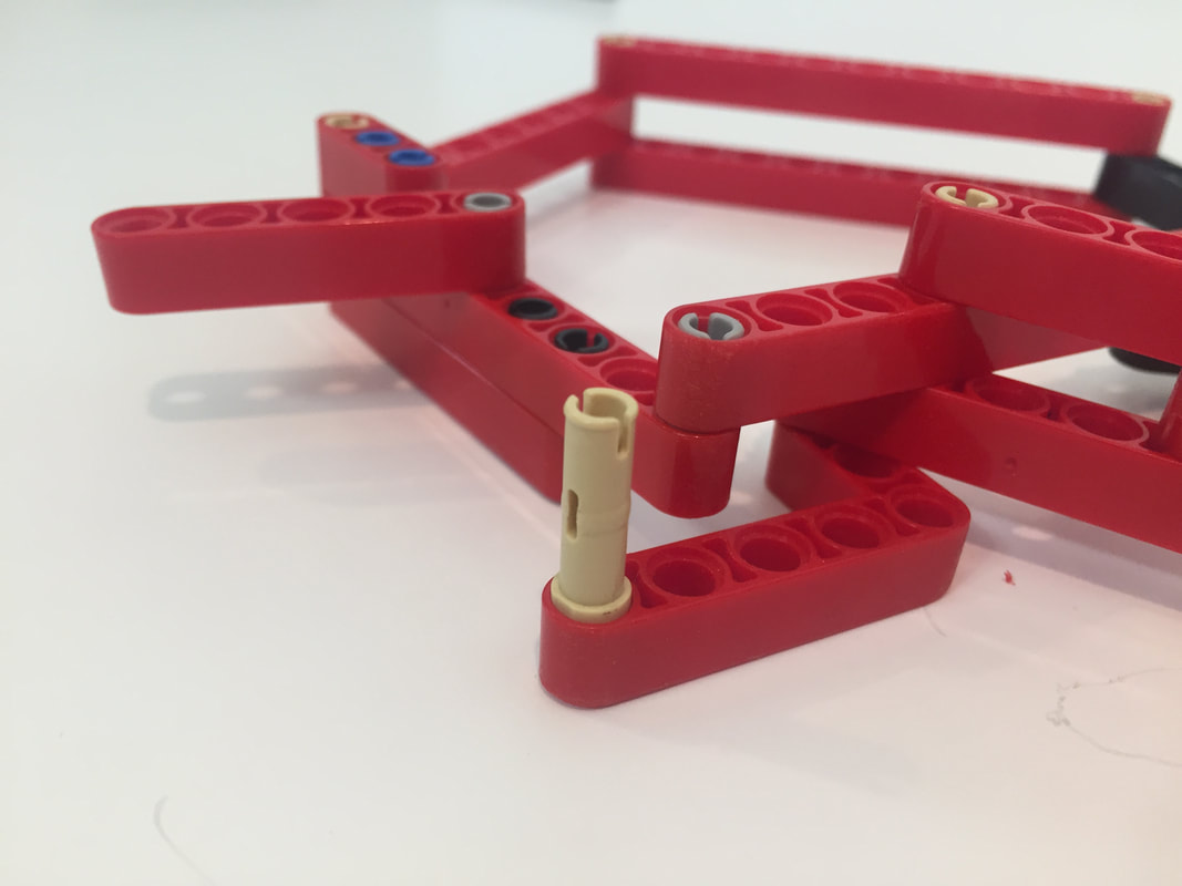
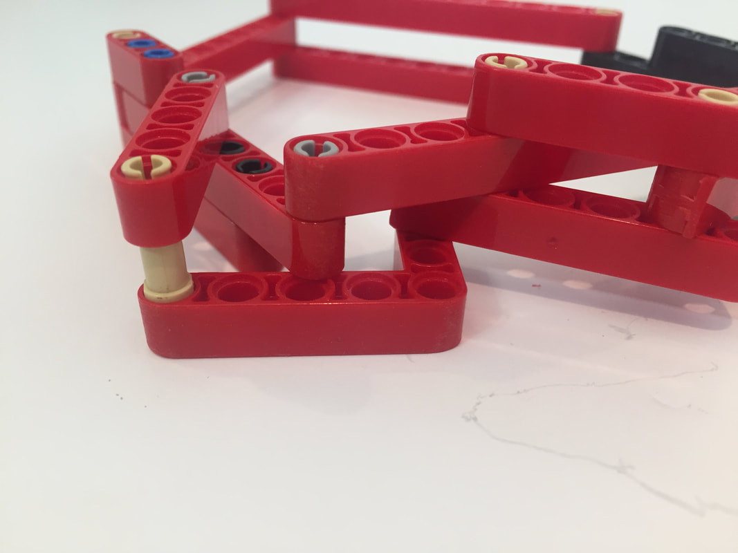
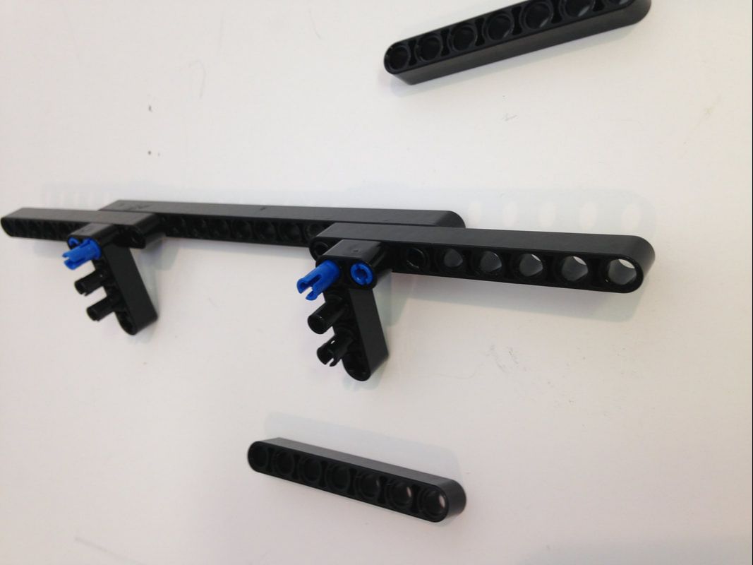
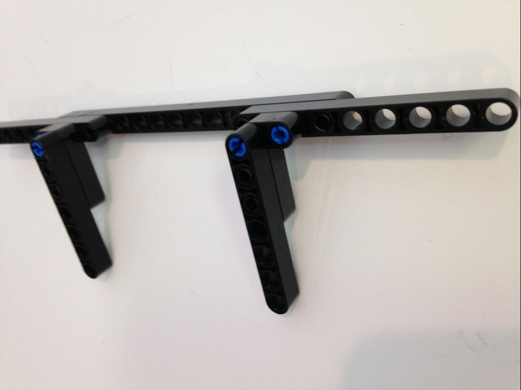
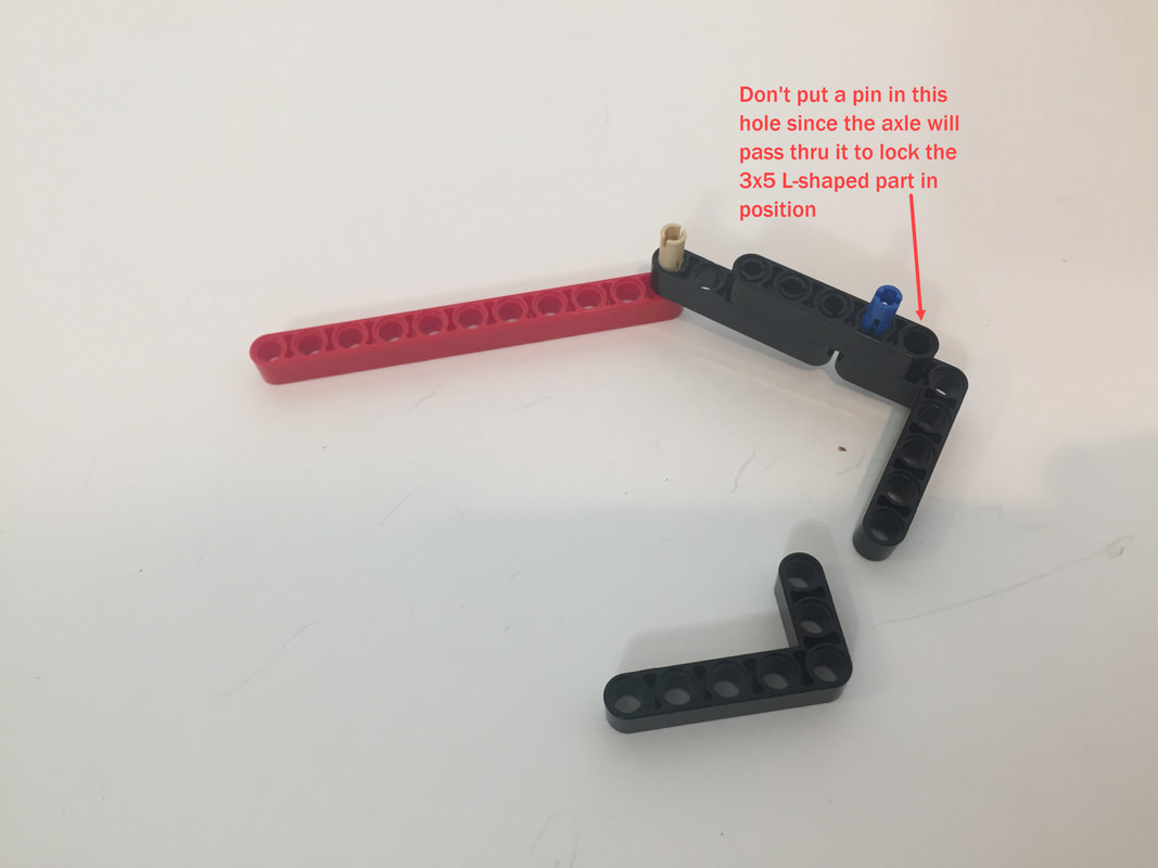
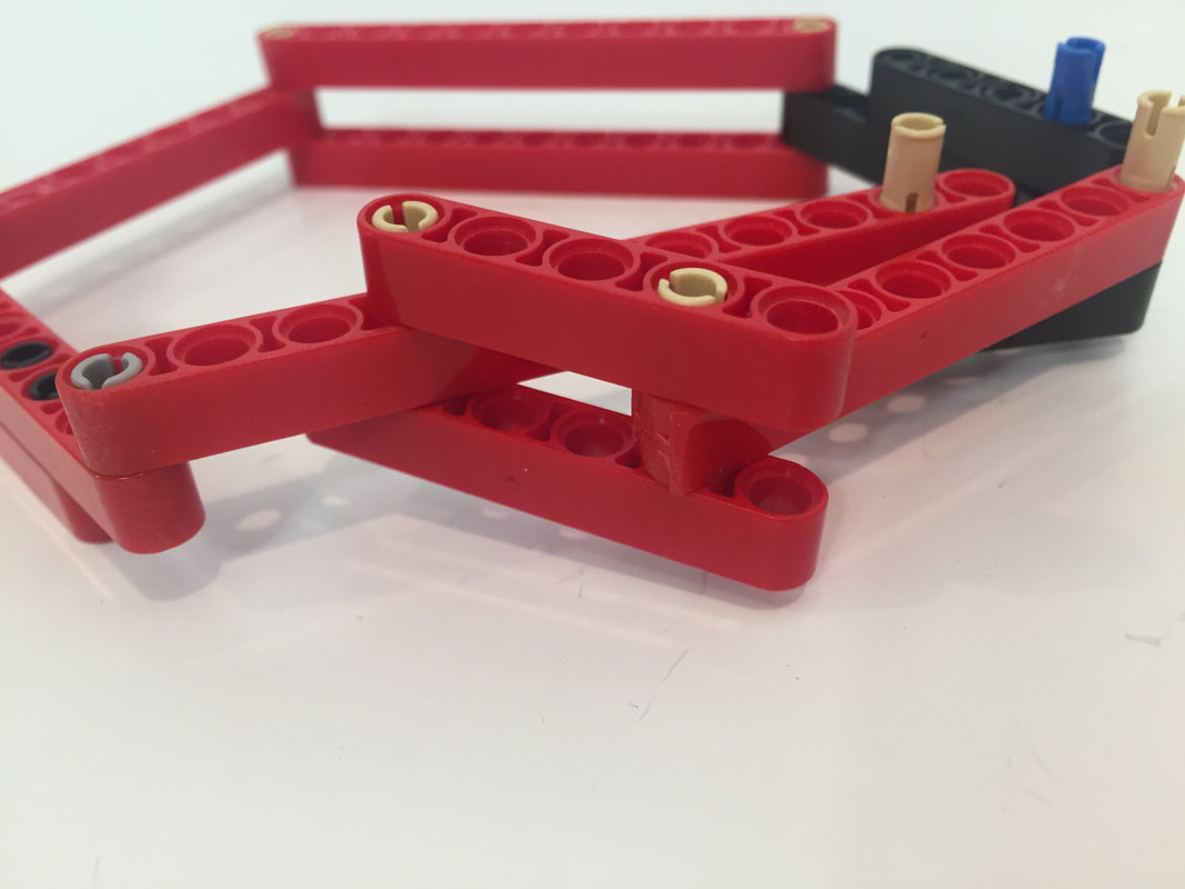
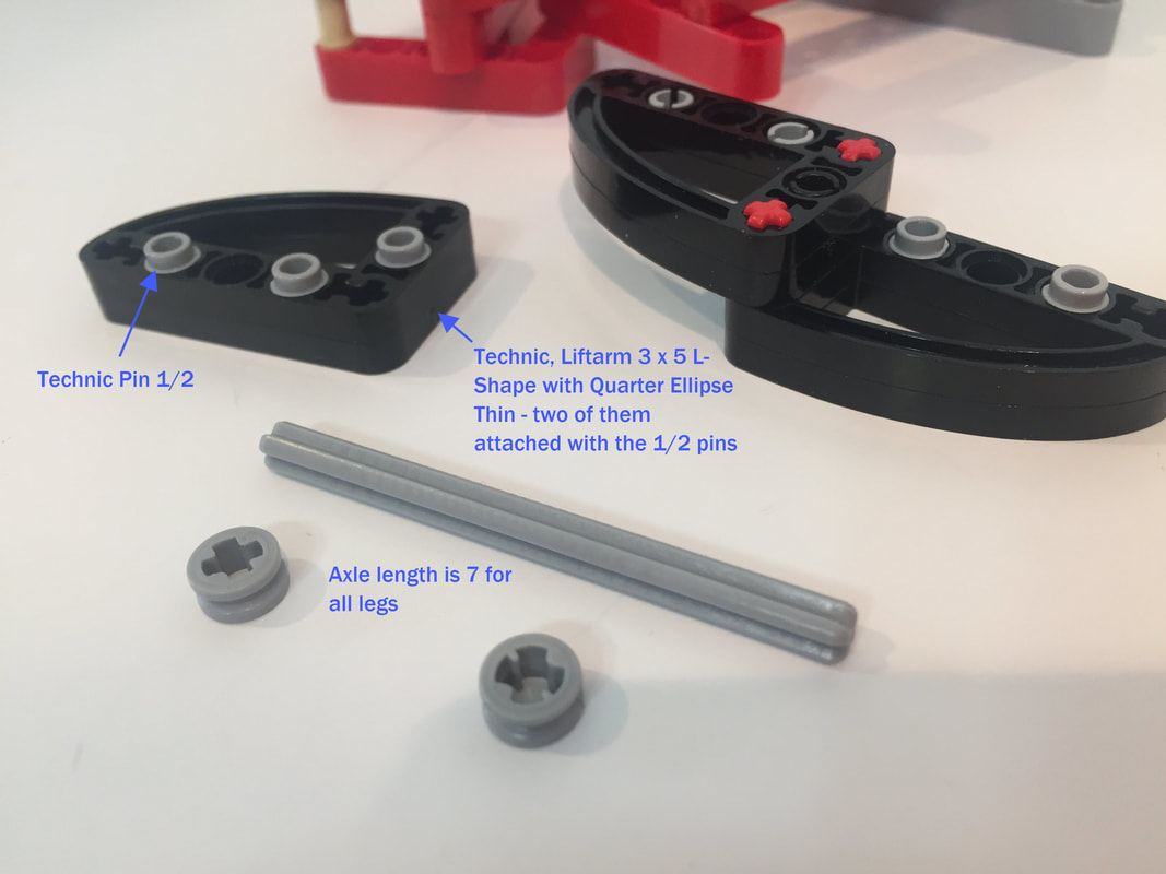
This 3x5 L-shaped part is the key to sandwiching the leg joints, which prevents the pins from pulling out during turns.
Next, I add the inner crank, and then the middle (double length) crank. I show how I made the cranks a few pictures down. The axle length for all 8 legs is 7 holes.
Make sure to avoid the below mistake:

|
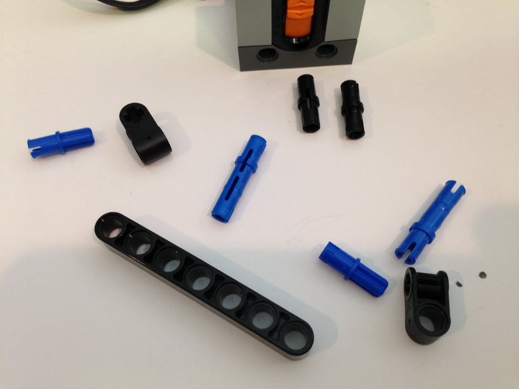
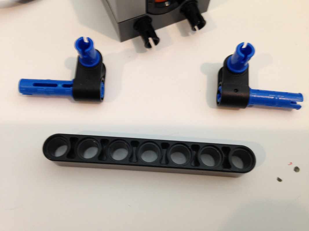
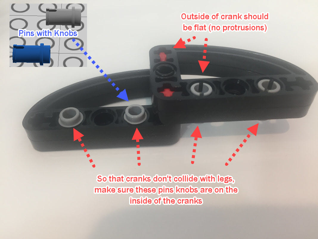
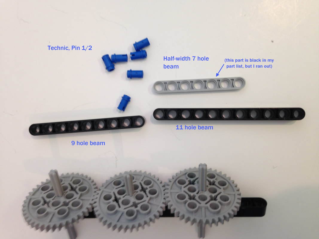
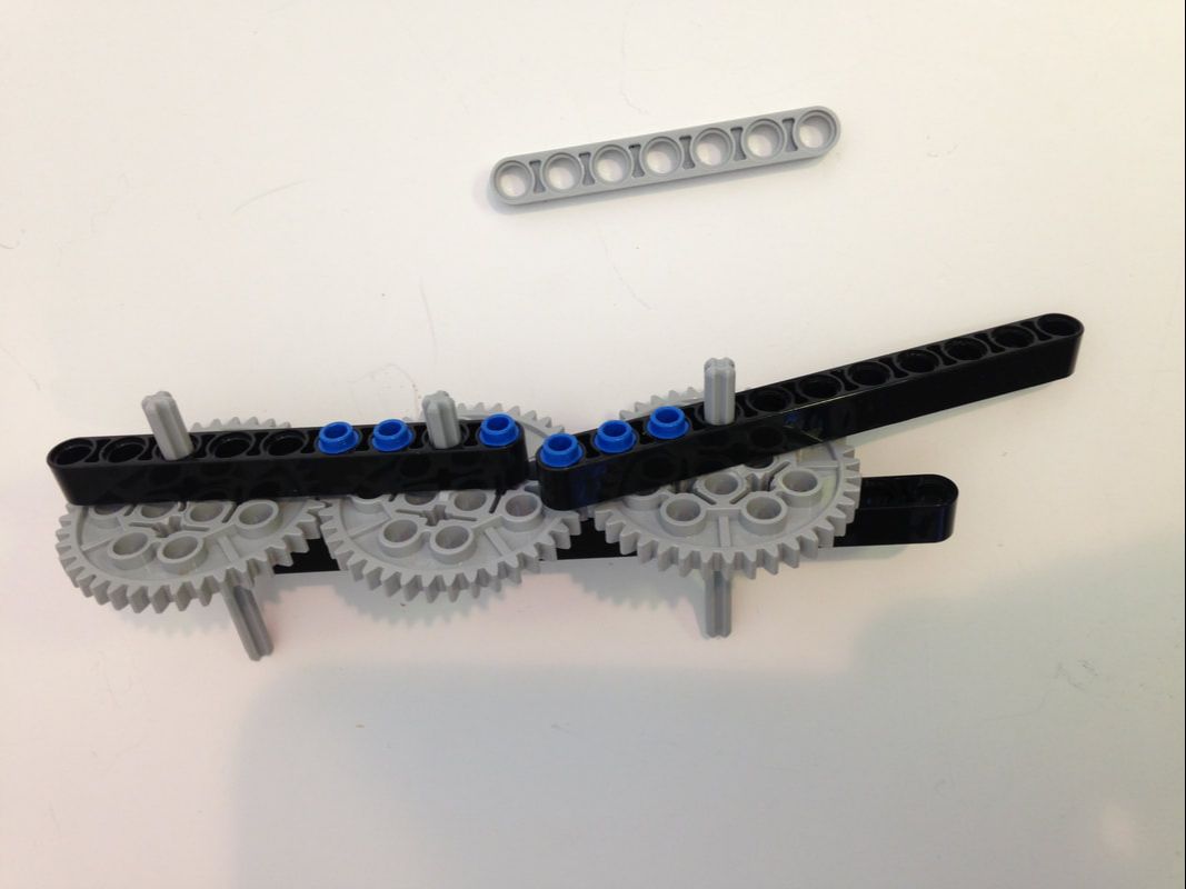
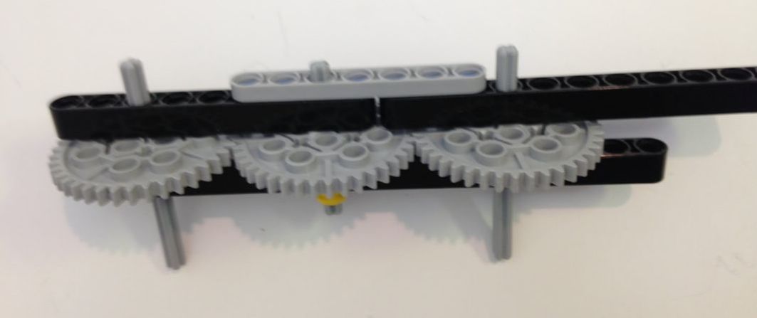
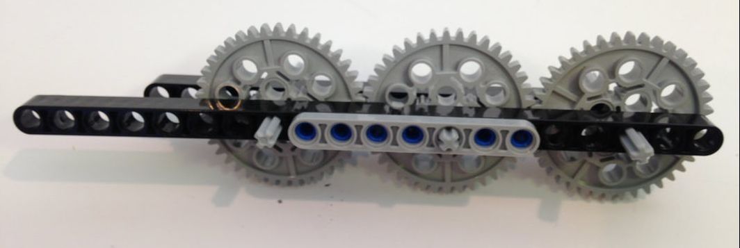
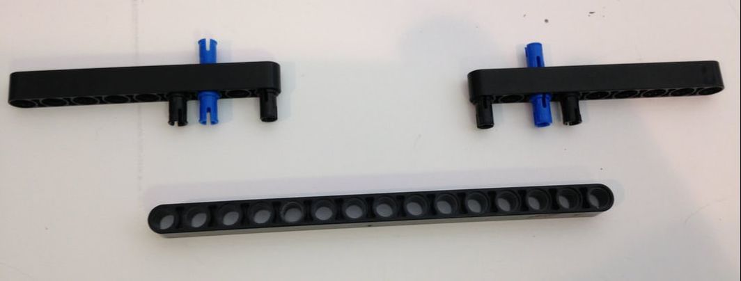
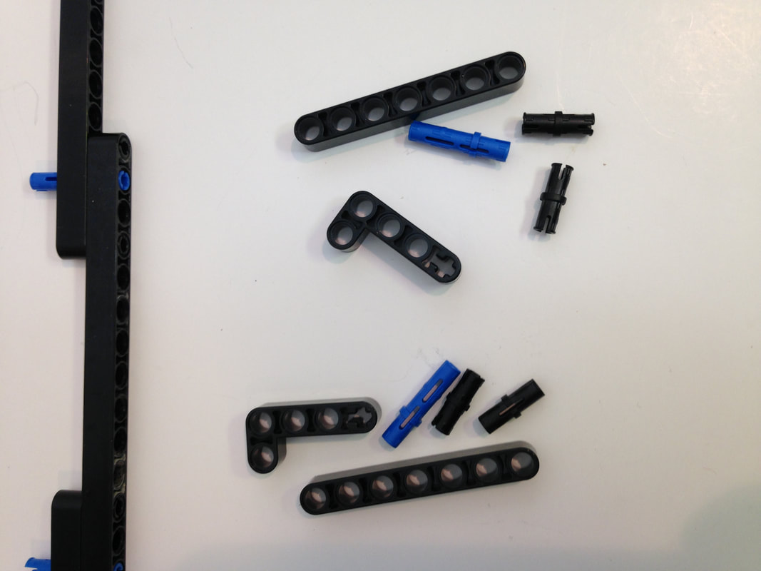
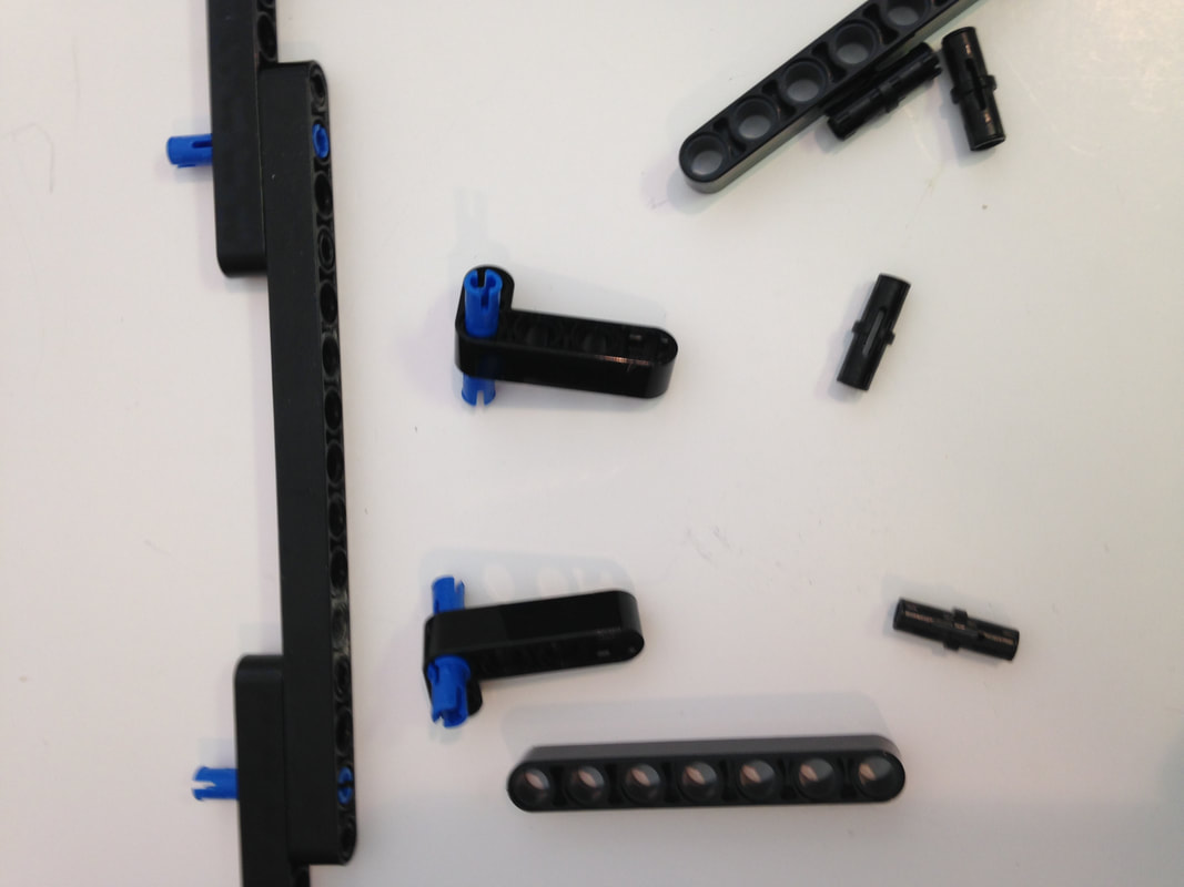
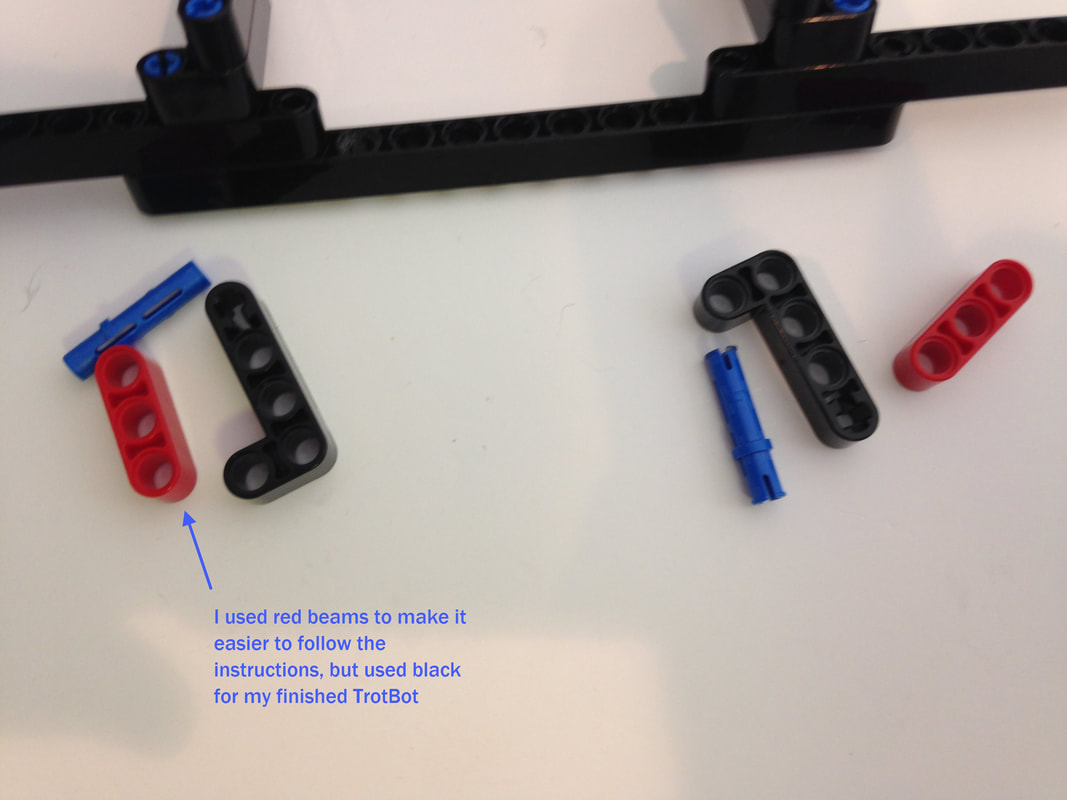
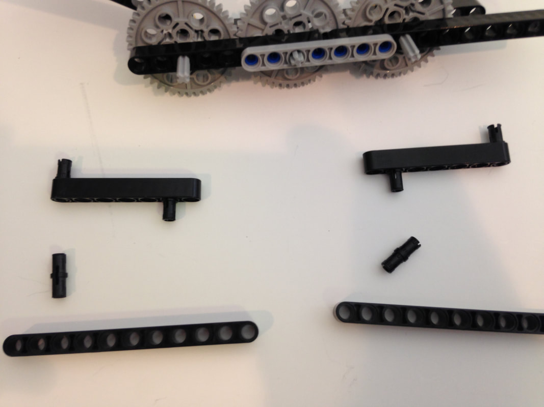
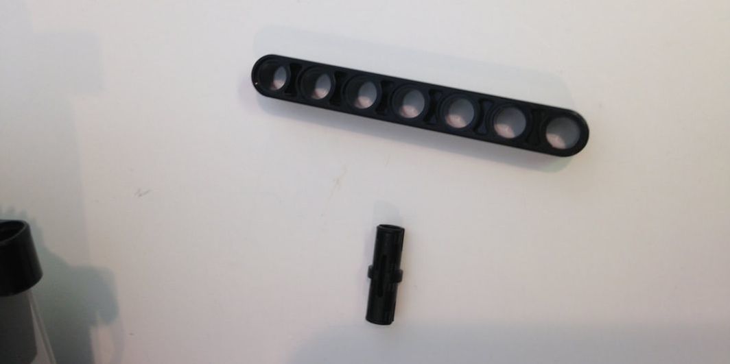
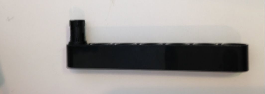
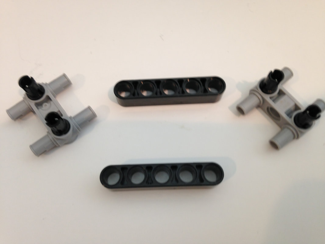
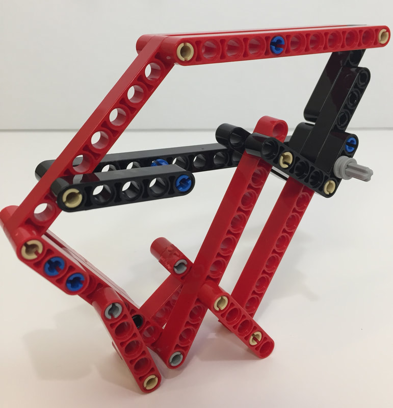
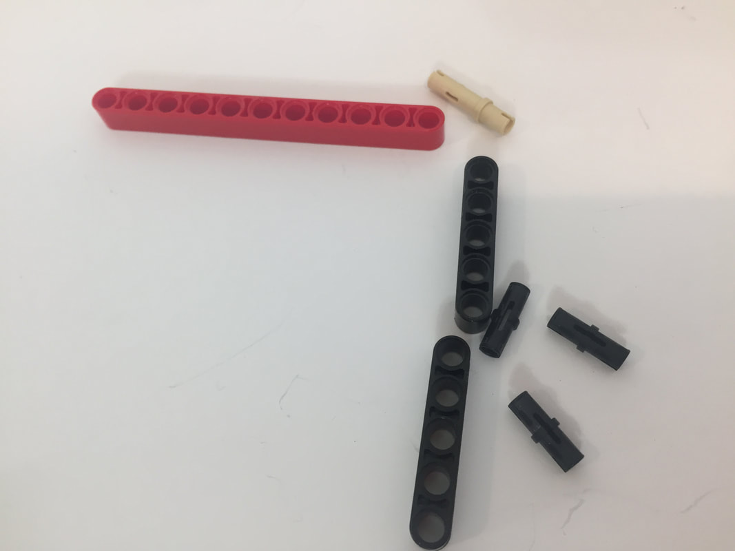
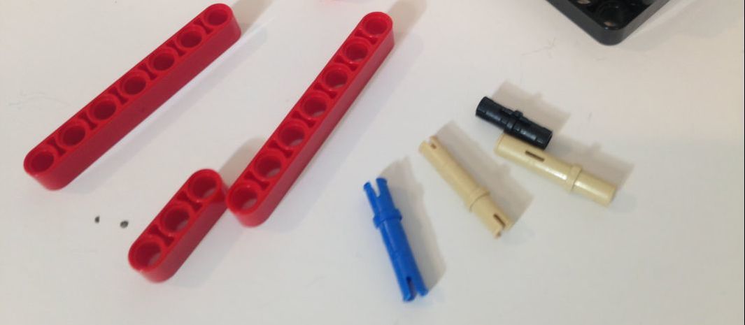
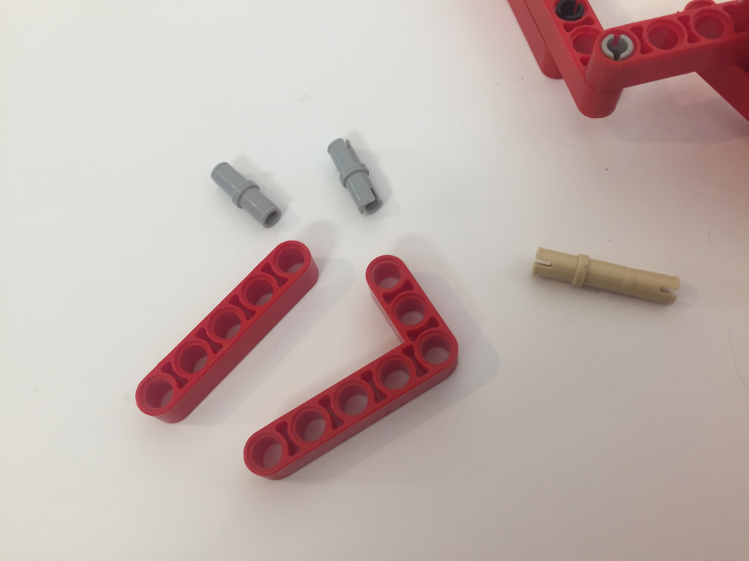
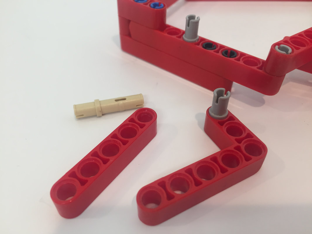
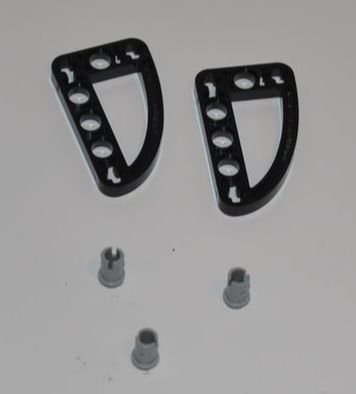
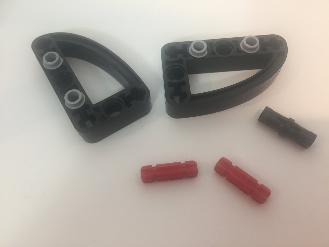
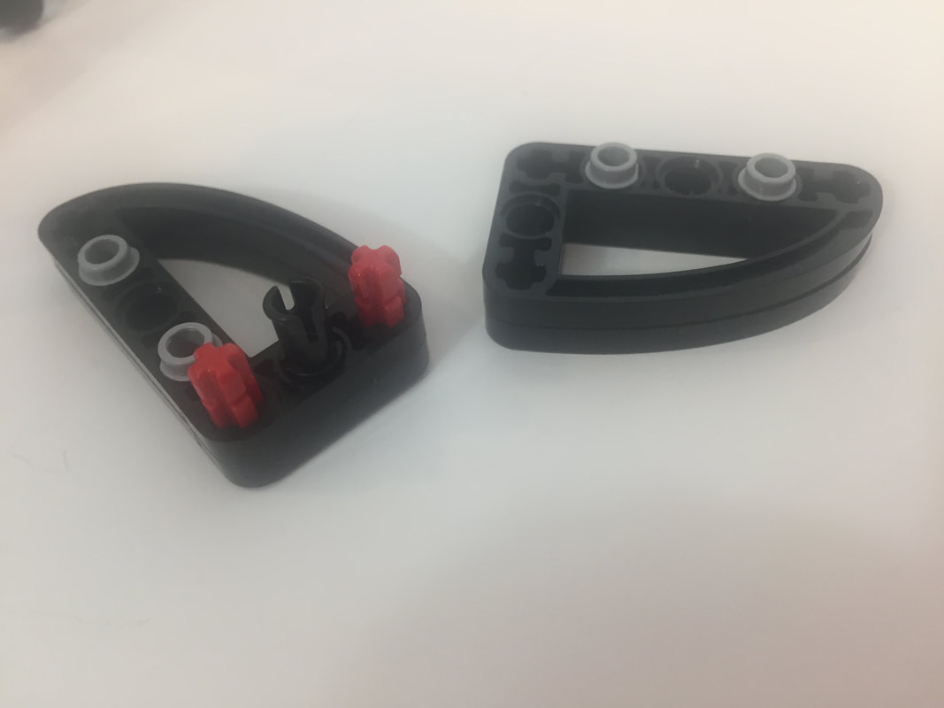
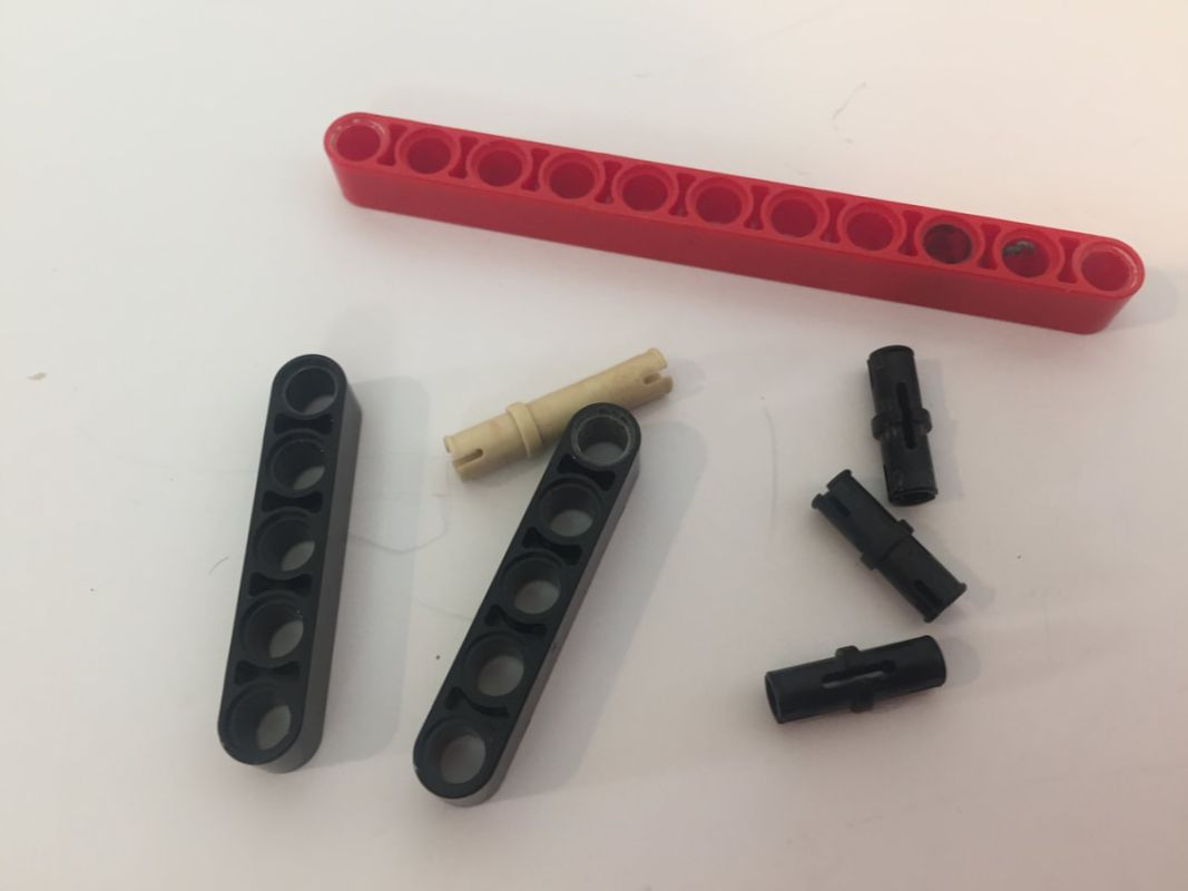
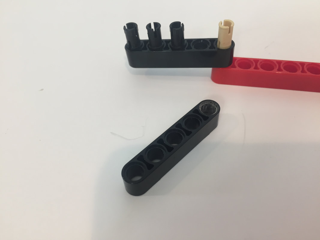
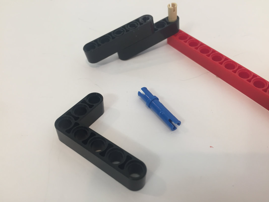
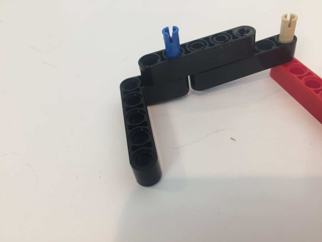
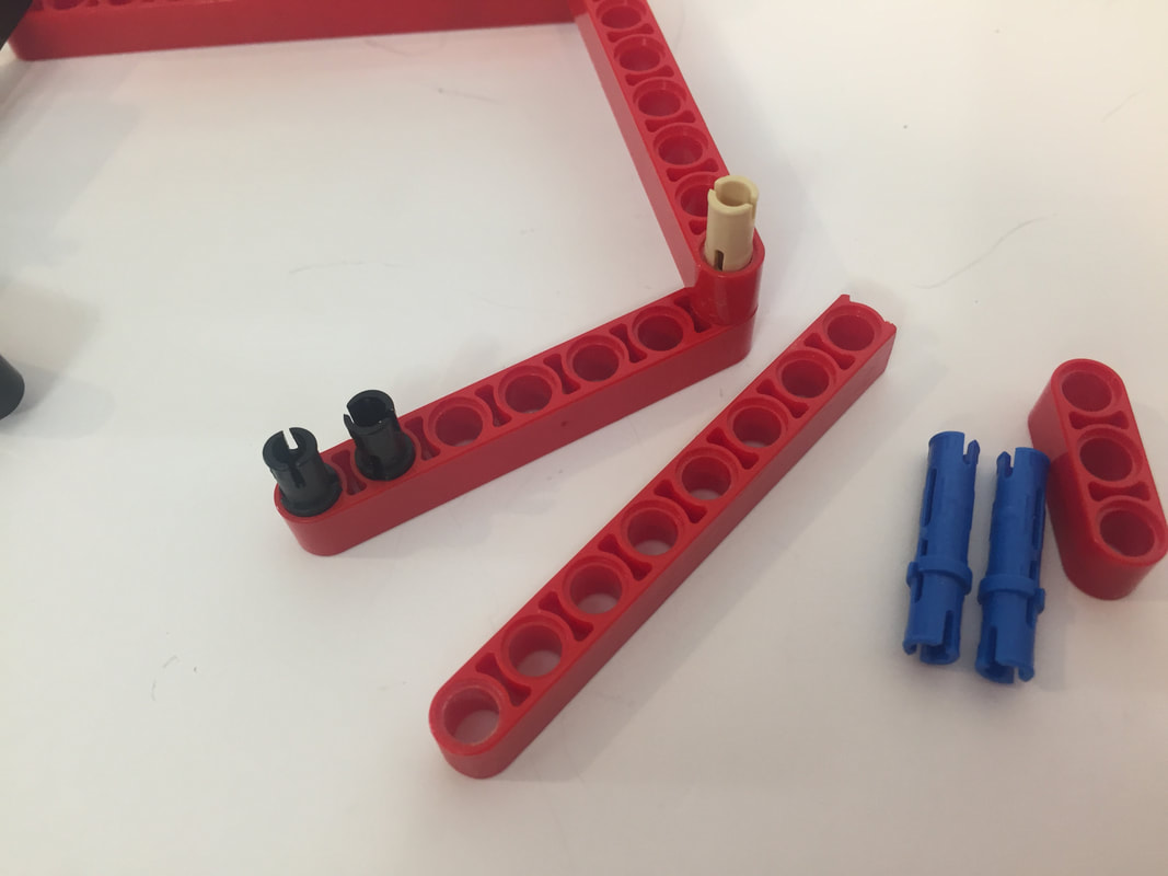
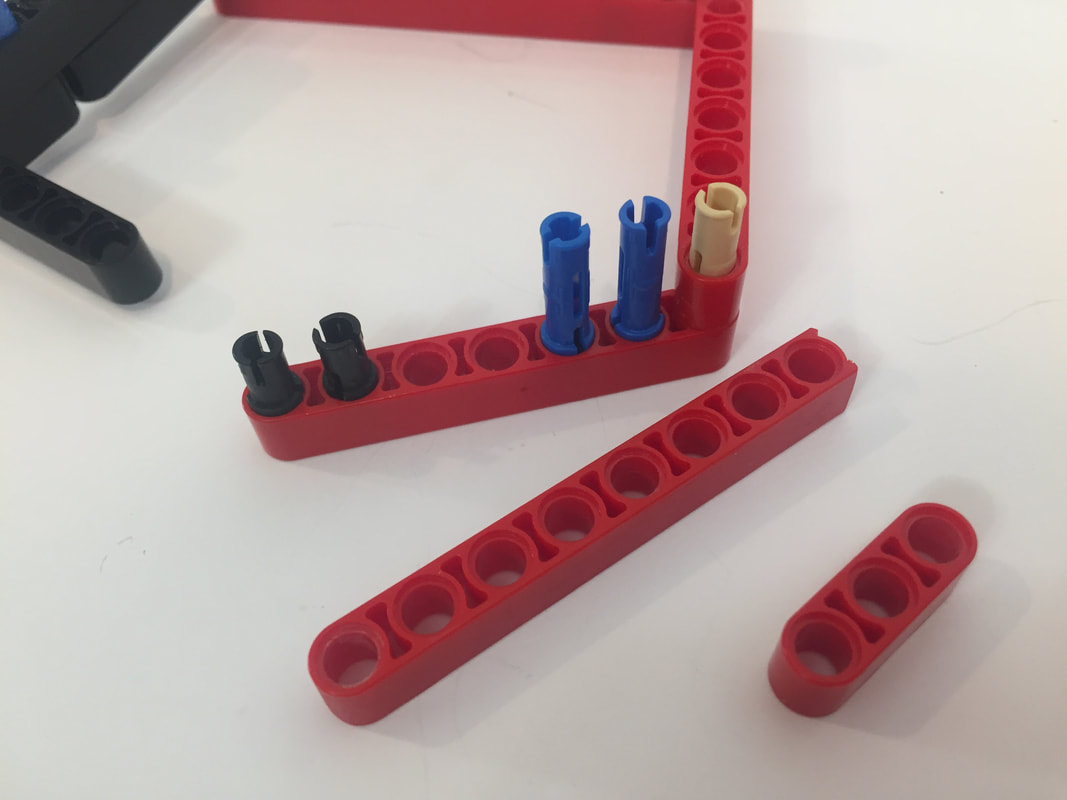
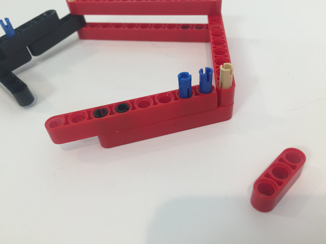
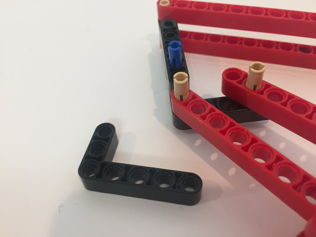
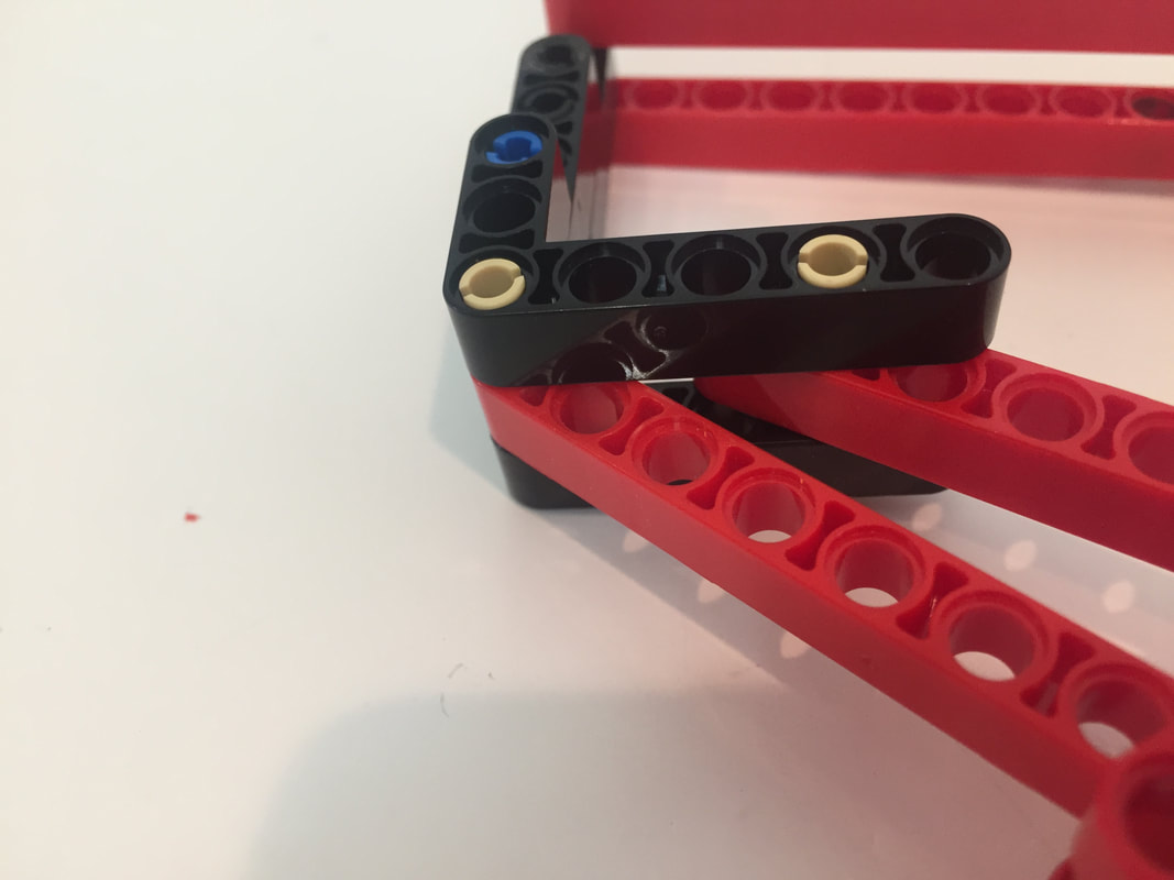
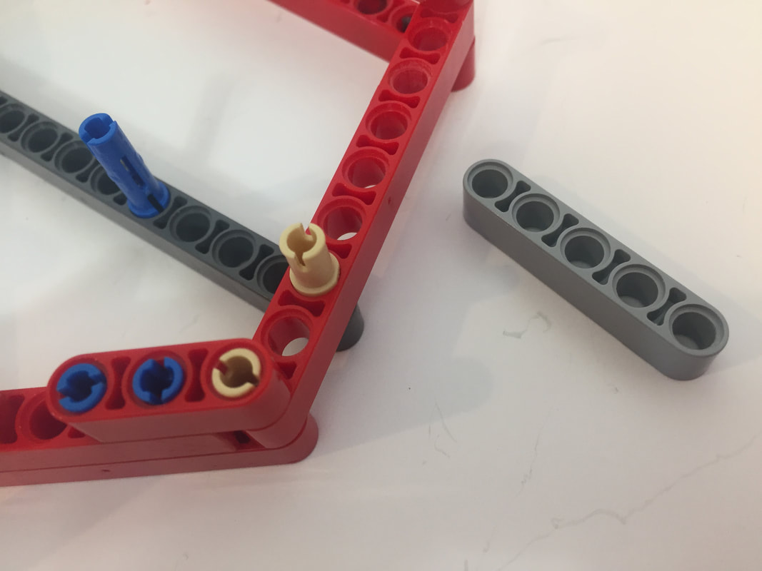
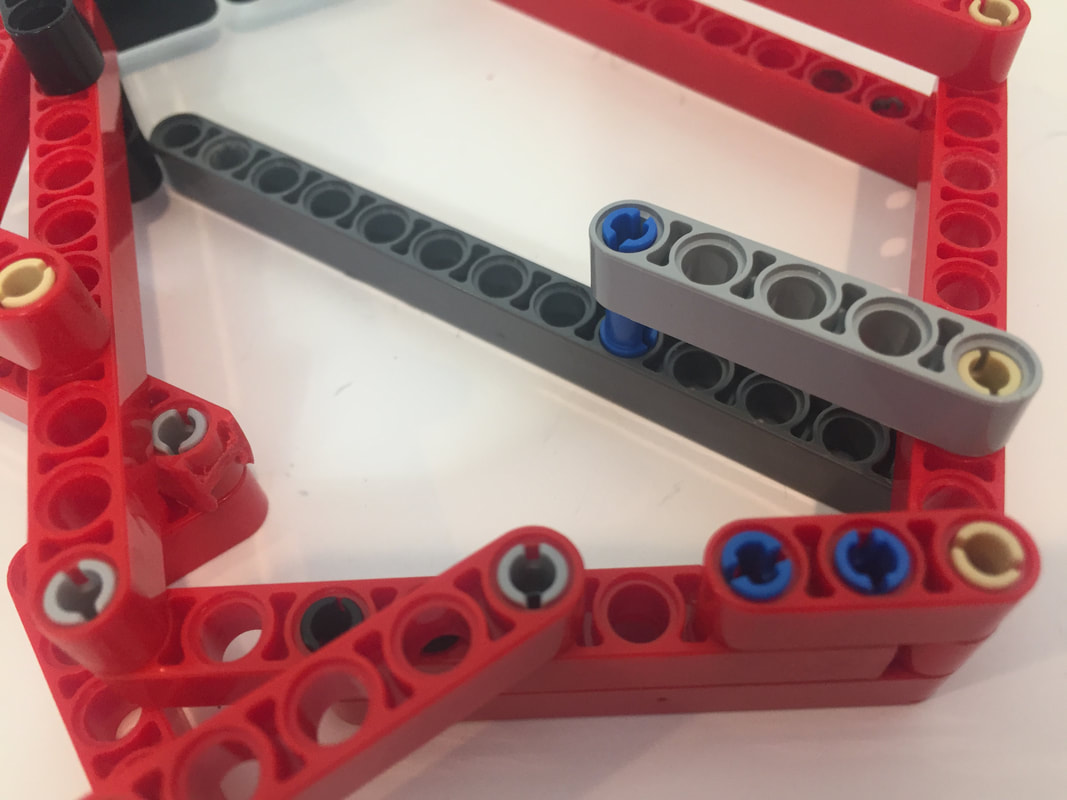
You will need to make a total of 8 single-length cranks, 4 to link the inner legs to motor's axles coming out of the frame, and 4 to link the outer legs to the outer frame. Here are the parts I used to make them. The cams are called "Technic, Liftarm 3 x 5 L-Shape with Quarter Ellipse Thin", and the pins are "Technic pins 1/2" (which were blue in my part list, but I don't think the color matters) |
|
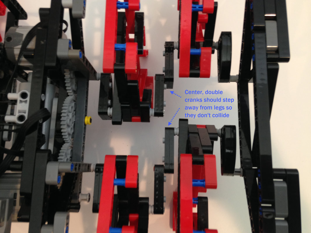
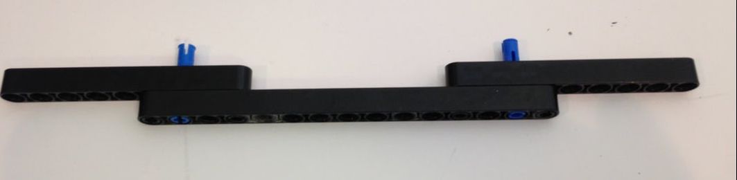
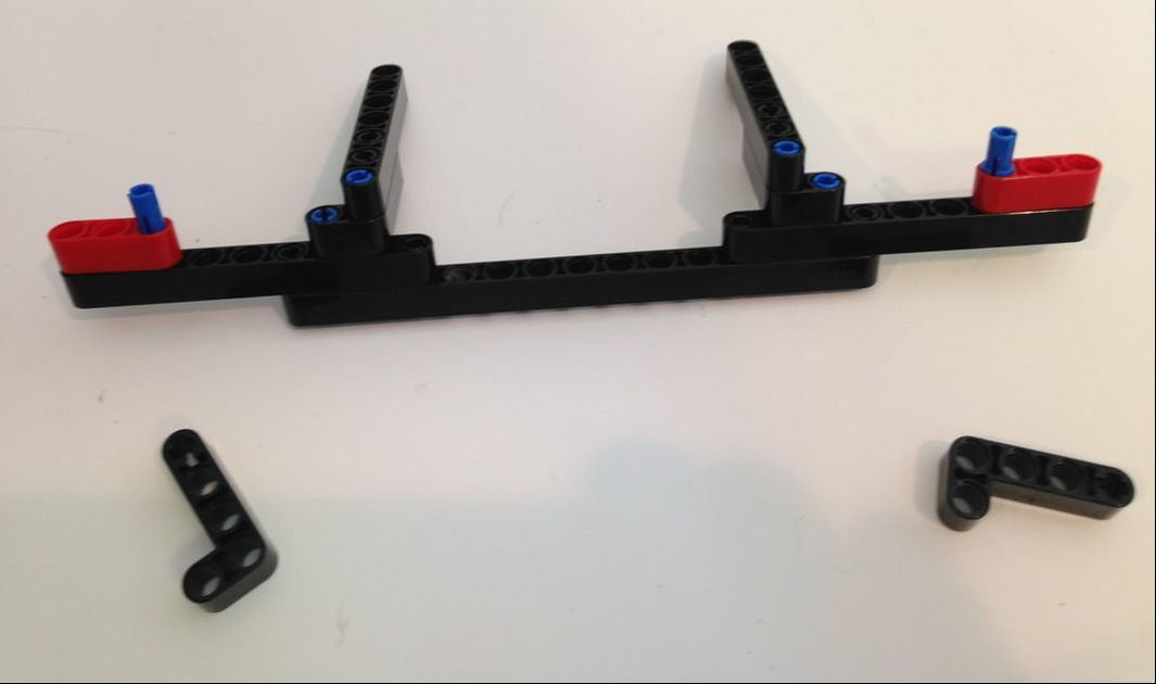
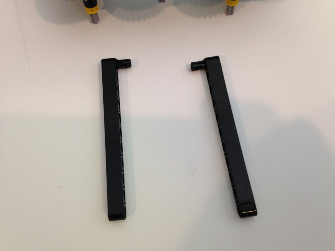
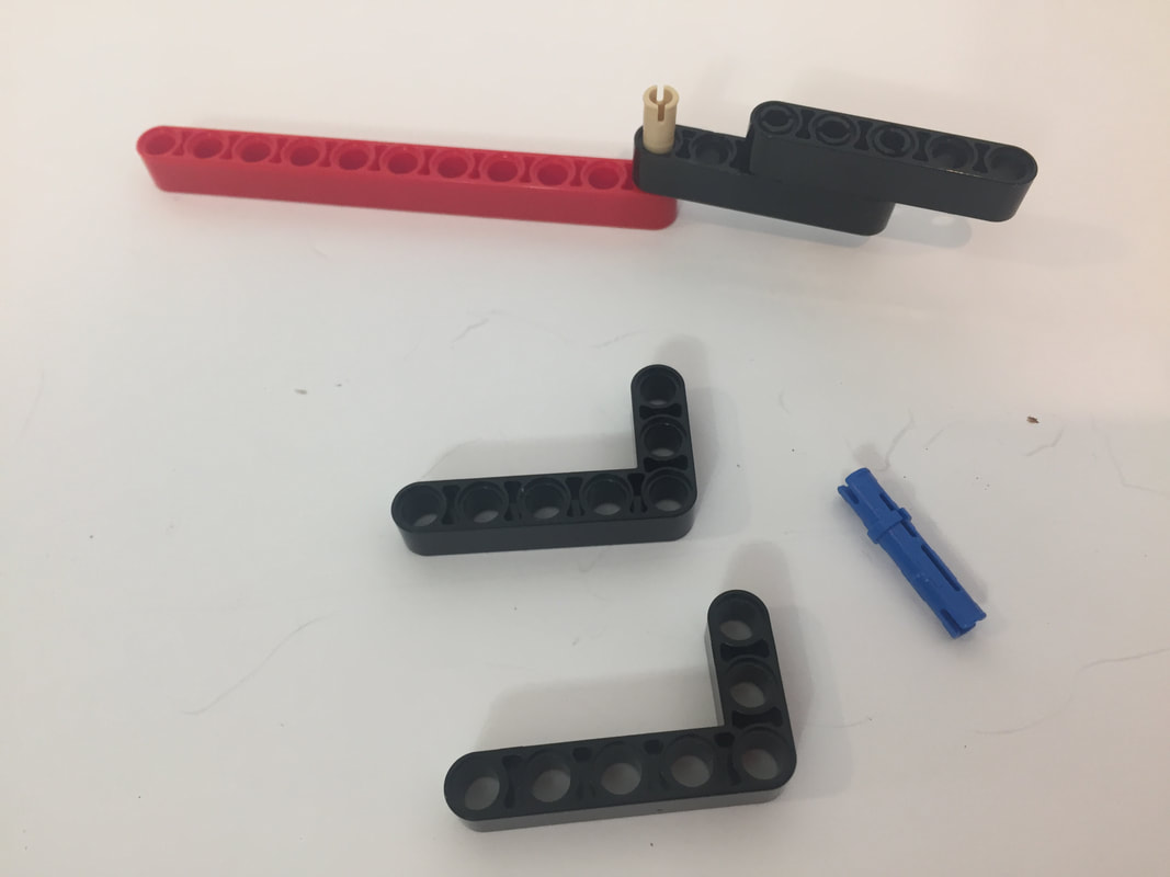
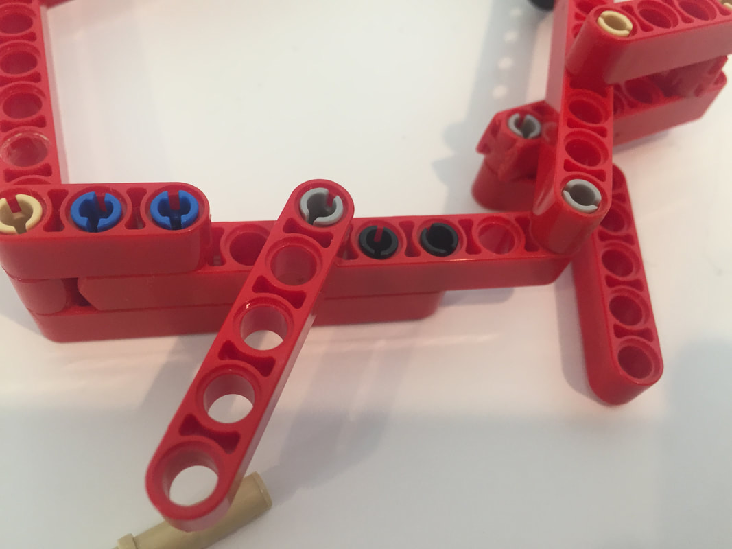
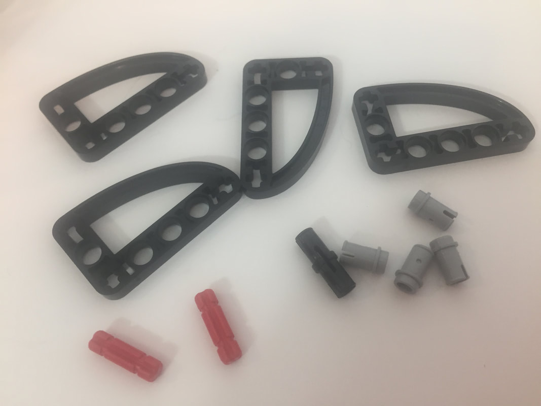
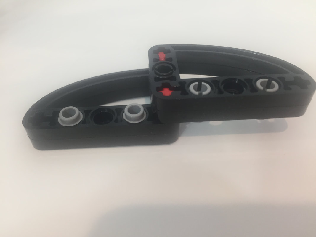
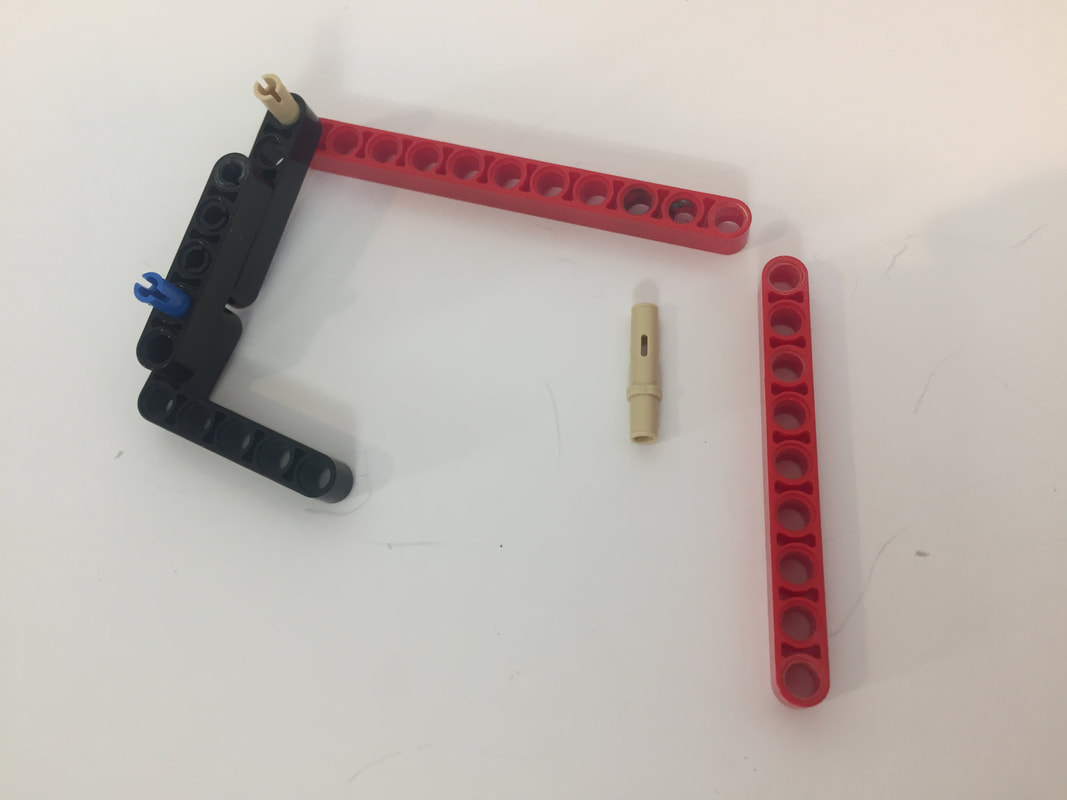
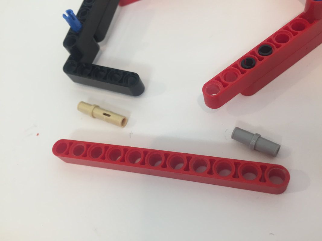
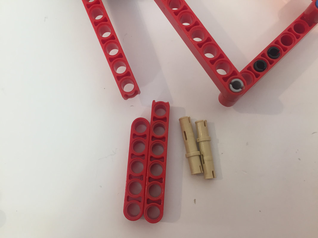
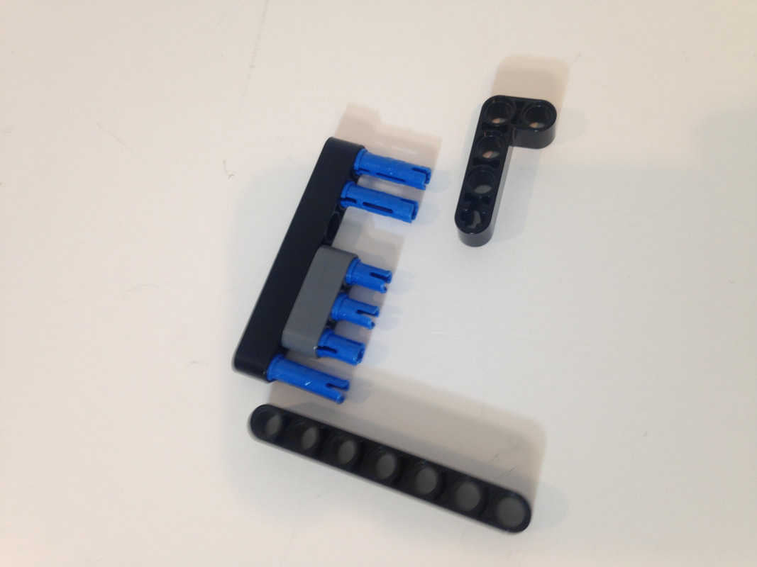
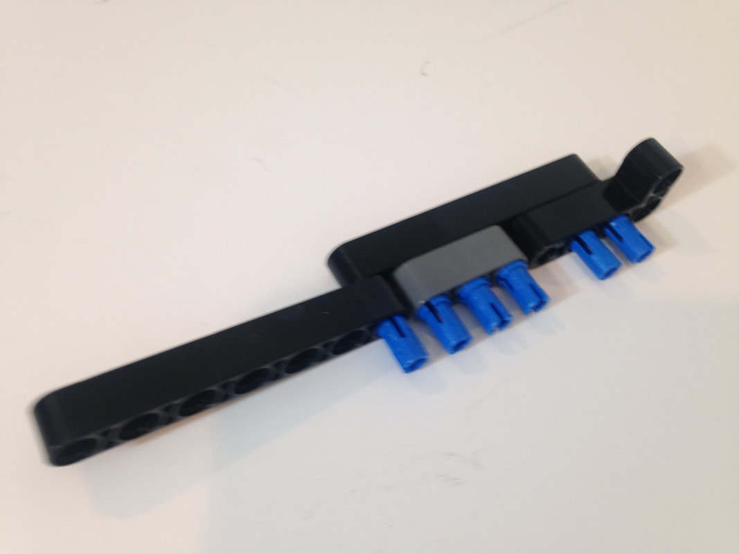
You will also need to make 4 double-length cranks that link the inner and outer leg pairs, which I build below. (the red parts are called "2m Cross Axle with Groove")
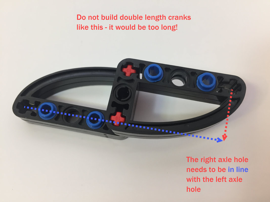
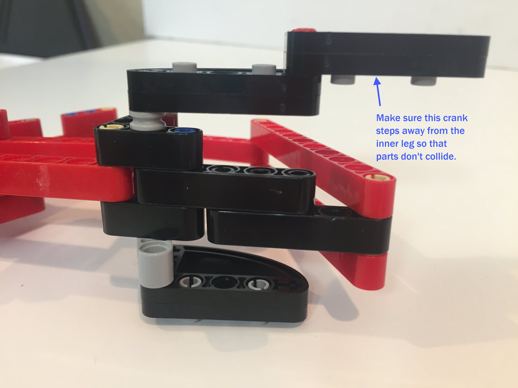
Notice that the double length crank (on top) steps away from the leg, which is critical to ensure the legs don't collide with the cranks. If instead the crank was flipped upside down, the leg parts would collide with it and lock the linkage.
Next I'll build the right-facing leg. You'll need to make 4 of them as well - unless you decided to simply make 8 of the left-facing legs.
Next, I build the front section of the lower legs, which I built from 3 beams to accommodate the retractable toe's linkage. The following picture (from the left-facing leg instructions) is how I recommend making them, and you do not need to cut 8 hole beams like I used 2 pictures down.
As I mentioned above you don't need to cut a beam to create an 8 hole beam like I used in the following pictures. Two 7-hole beams and one 3-hole beam are fine for making this leg section (as shown above).

Next, I add the retractable toe:
And then add the cranks in the same manner as the left-facing legs.
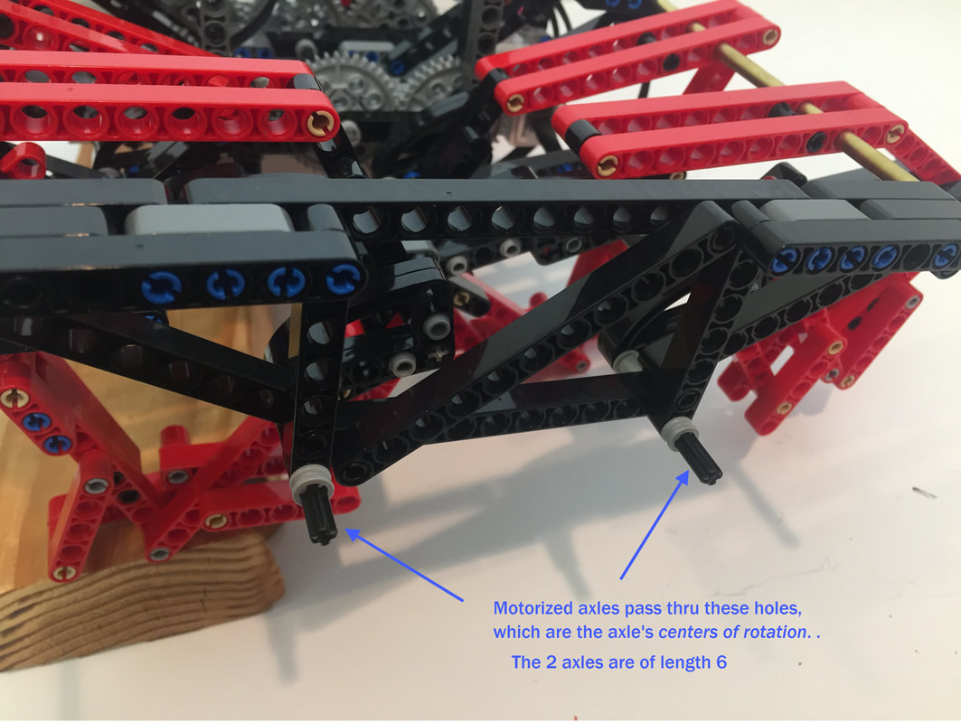
Next I show how to build the outer frames. You'll need to make 2, one for each side.
Next I show how to build the outer frames. You'll need to make 2, one for each side.
Notice there are no LEGO pins in the lower corners since the two motorized axles will pass thru these holes, as you can see below.
Hopefully the following pictures make it clear how to put the legs on the robot - NOTE: the following 2 pictures are from my EV3 instructions, but the legs and cranks for both builds are the same. As you will see, it's easier to slide the legs on by slightly rotating them on the metal rods (or rotate the rods).
The left and right sides should be mirror images of each other (picture from EV3 instructions).
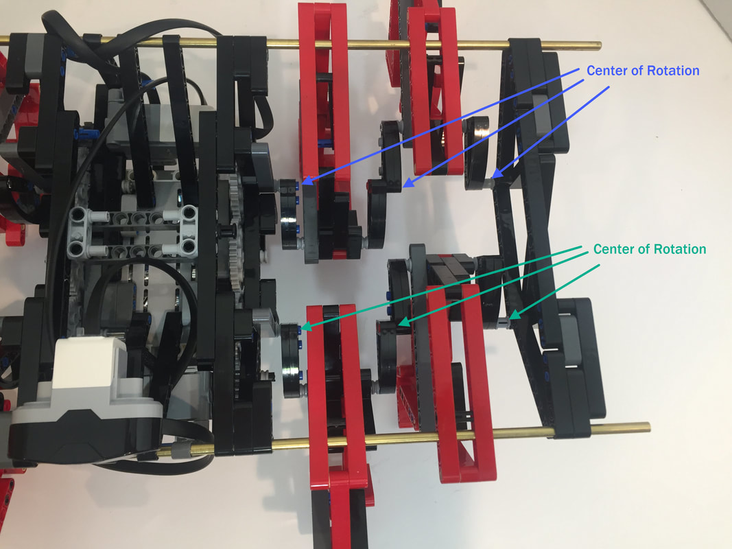
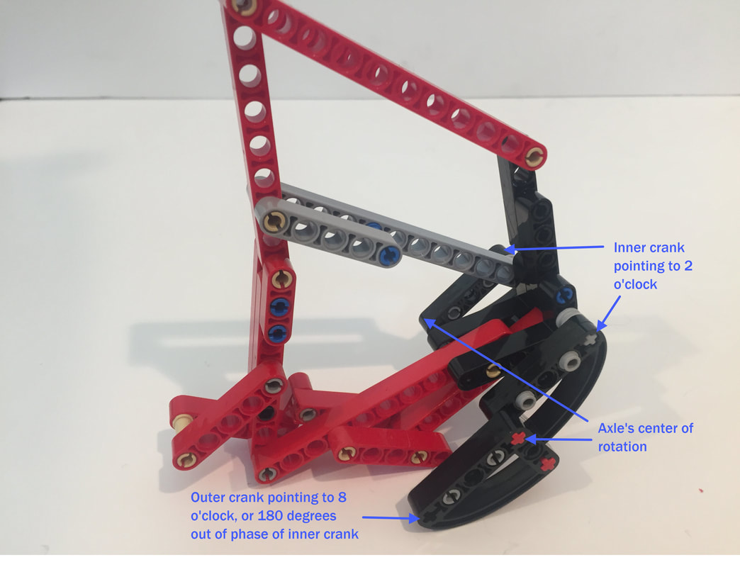
Make sure the front leg is in the same phase as it's rear leg - in other words, if the front crank is pointing at 12 o'clock, then so should the rear crank. NOTE: you may need to loosen the gear train to get the front in rear legs in the same phase. Also, make sure you attached the middle (double length) crank so that the inner and outer leg pairs are 180 degrees out of phase, and that the outer cranks return the outer axles to the center of rotation.