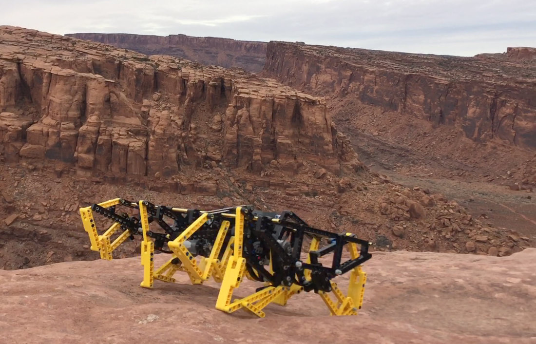
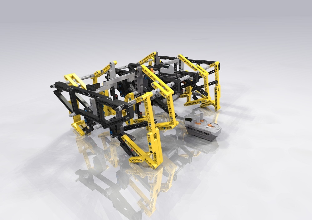
TrotBot, Ver 1
UPDATE: For stronger legs, use the attachments described in this post which allows TrotBot to turn on high friction terrain without the leg's pins coming out - the below video is an example.
|
UPDATE #2: Here are some simplified instructions for building TrotBot's leg mechanism with retractable toes, which results in a smoother gait and lower torque requirements. This leg will work for all 8 legs of TrotBot. |
Let's build it!
Overview
Linkage: TrotBot uses the linkage developed by Team TrotBot
Build Difficulty: Hard. There are simpler ways to build TrotBot in LEGO, but I chose to post the most robust version I've built. This heavy-duty build carries its battery pack for remote operation along with 2 motors for steering and climbing torque, and managed to survive 2 days of kids running it over obstacle courses, piling wood on it, and general rough play at the World Maker Faire.
Trobot's Characteristics:
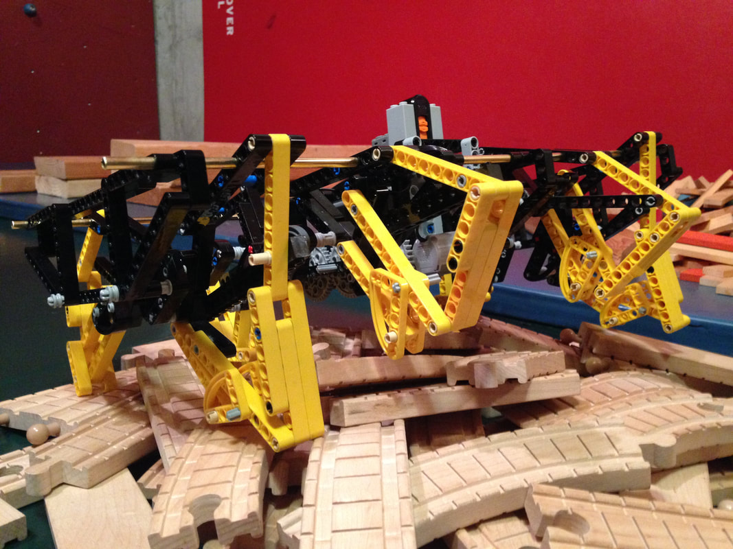
1. 8 Legs, or 4 "horses" with a gait that mimics a galloping horse
2. Walks most efficiently with the addition of a "heel" on both smooth and rough terrain.
3. Steerable? Yes, by driving one side forward and the other in reverse, like a tank.
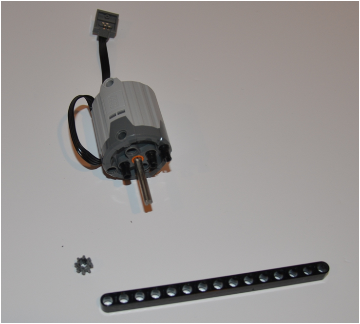
Parts Used: In addition to the Technic beams, pins, gears, etc., this build uses LEGO's Power Functions IR RX 8884 remote receiver which I controlled with a 8885 IR remote, 2 LEGO Motors, and a 8881 Battery Pack. You can use either LEGO's 8883 medium motors for a faster TrotBot like this, or, if you want higher torque so TrotBot can handle rougher terrain like the below stair climbing video, then use LEGO's half-speed, 4x torque XL 8882 motors.
For TrotBot's 2 support rods I used 3/16 inch OD Brass tube, but solid aluminum rods work fine as well and may have less risk of bending. Both rods were cut to 16 inches in length, and be sure to file the cut smooth so that the legs parts can slide on easily.
I purchased the plastic LEGO parts from Bricklink
I purchased the motors, controllers and battery box from Amazon
I purchased the metal support rods from my local hardware store
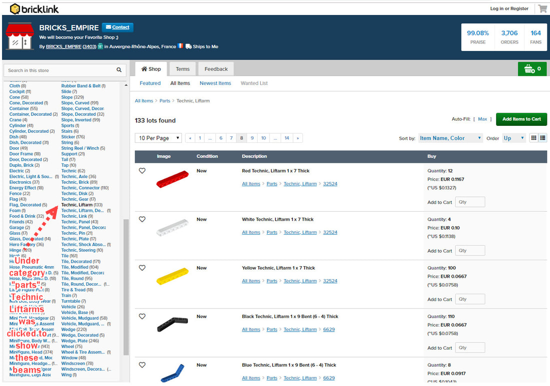
If you've never used Bricklink, an easy way to browse for parts is by going to a larger store. Here's a list of stores in the USA.
And below is an example search in a store for Technic beams.
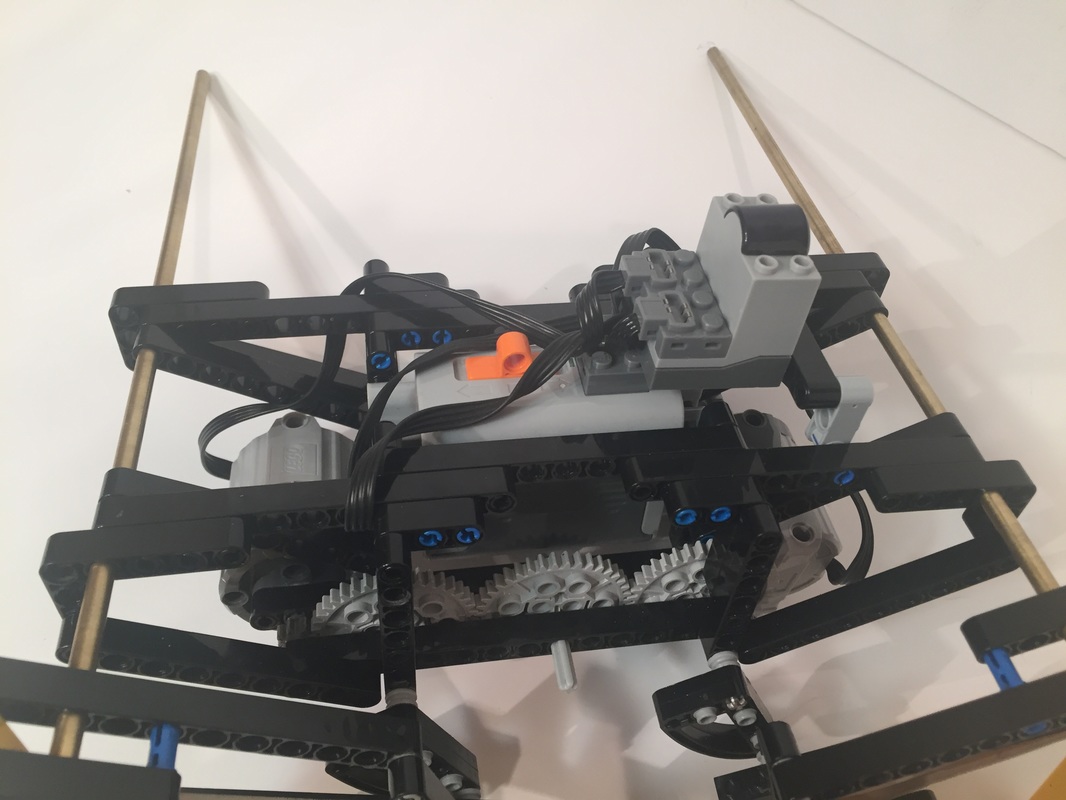
UPDATE: I Recommend mounting the battery box lower than described in these instructions, which I did in version 3. I haven't updated the following instructions yet, but I posted how to mount the batter box lower in my blog. By lowering TrotBot's center of gravity it handles better, and climbs steeper obstacles without flipping over as easily.
Trouble Shooting a Finished TrotBot
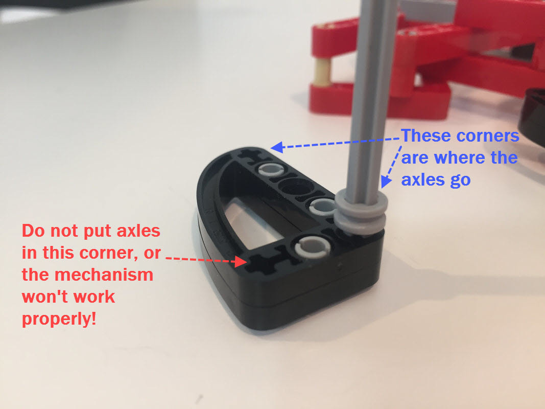
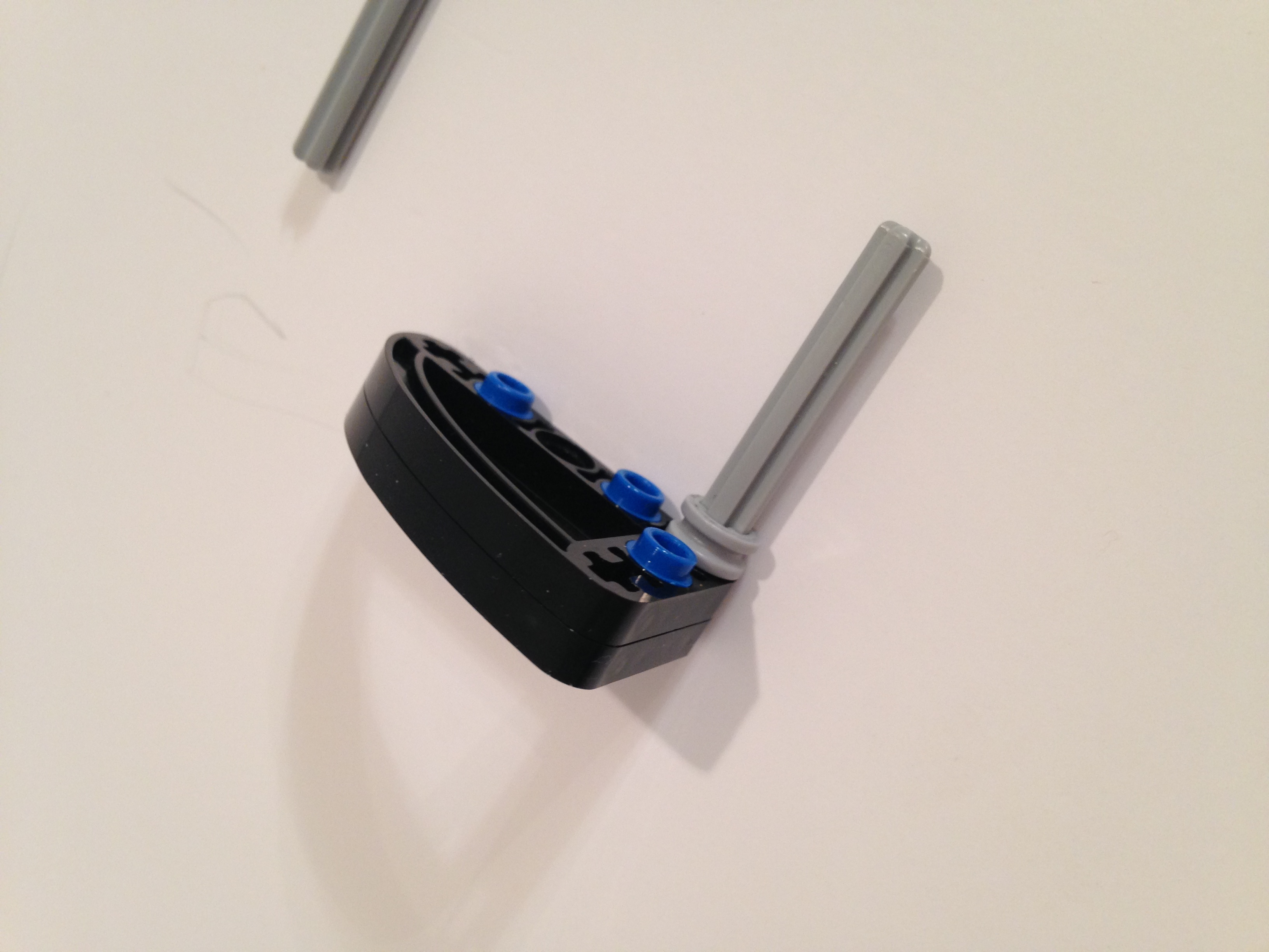
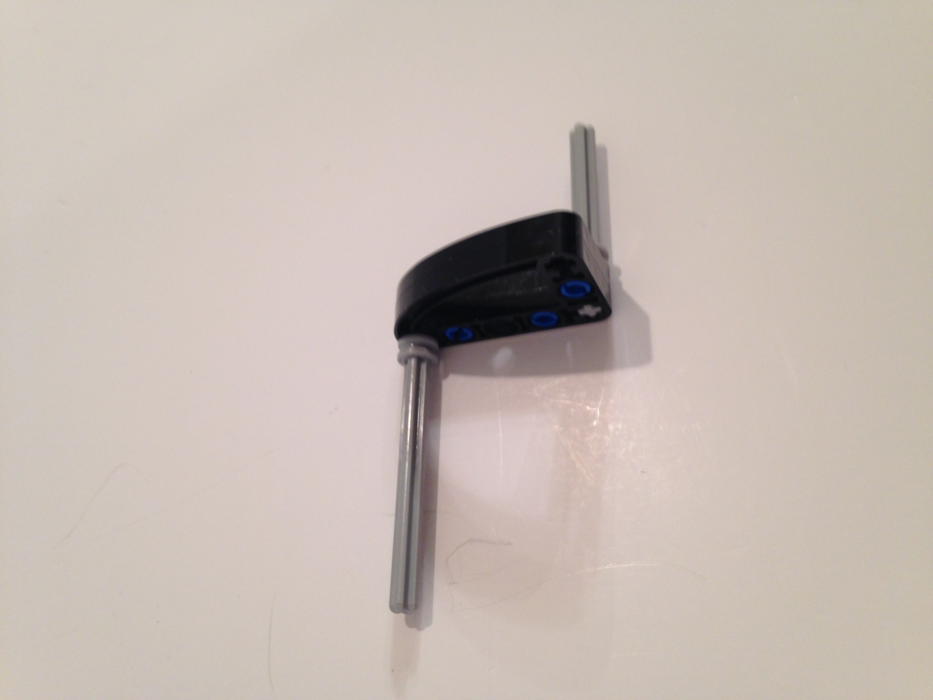
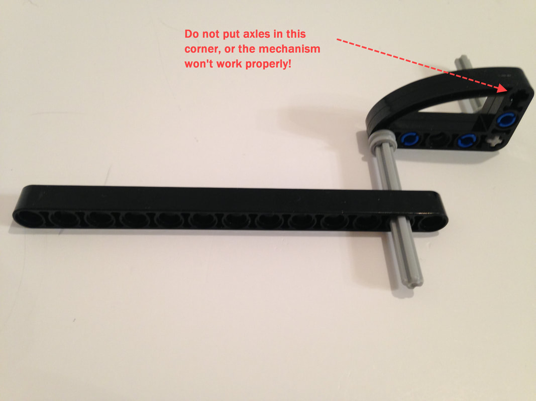
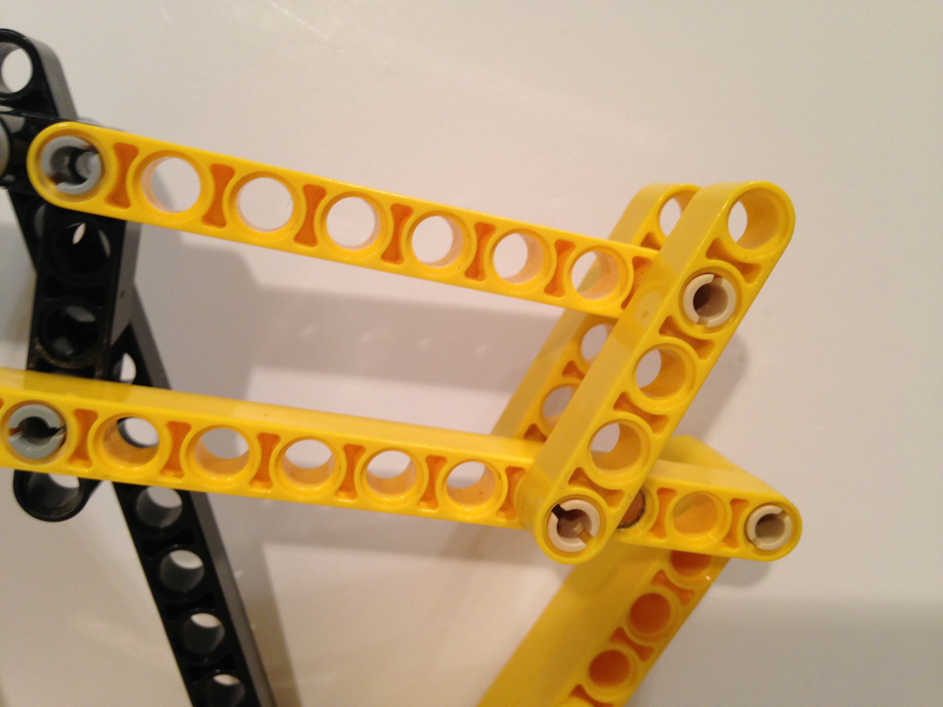
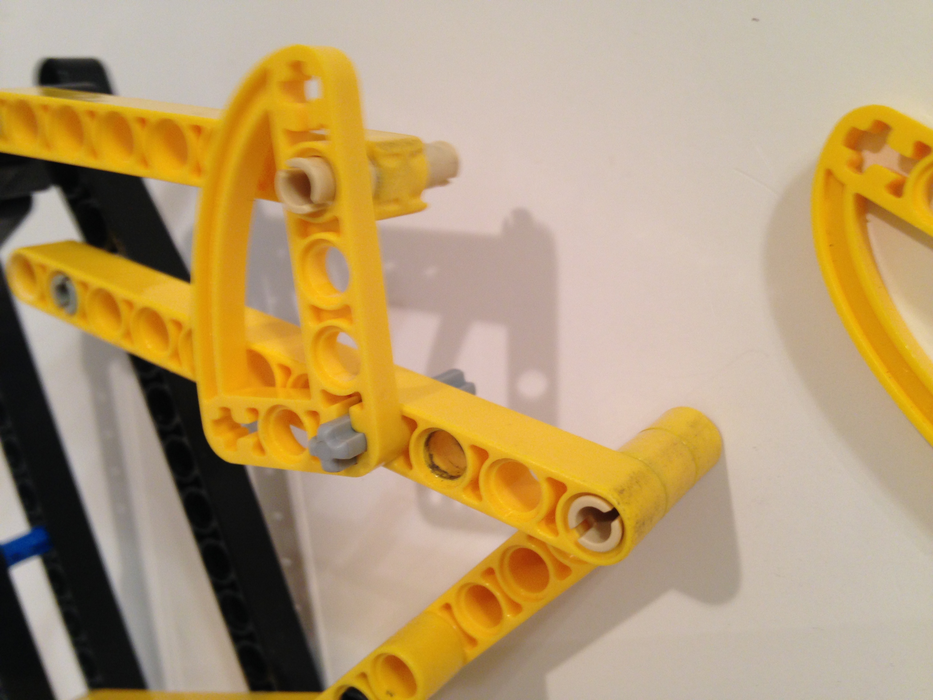
A finished TrotBot's legs should be easy to rotate by hand with the motors disengaged. If you feel resistance, then look carefully at the legs to see if any look asymmetrical or skewed. Also, an easy mistake to make is to put the axles thru the wrong hole of the 3x5 cam part below. If the legs aren't working properly, check your cranks.
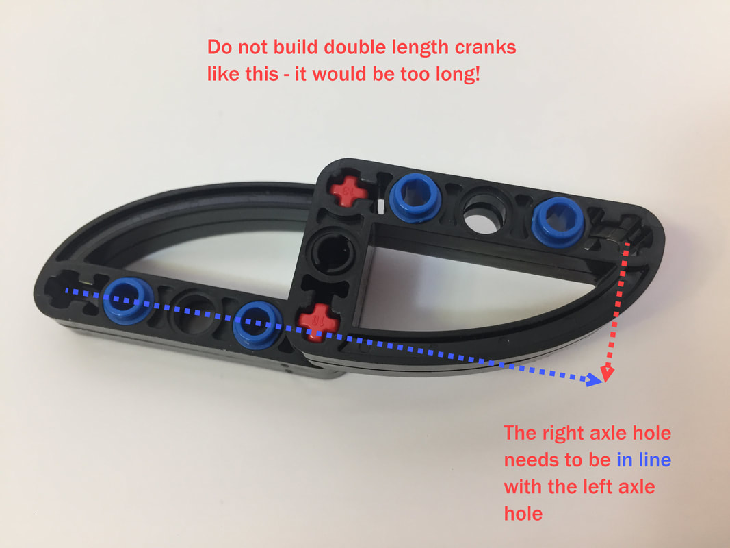
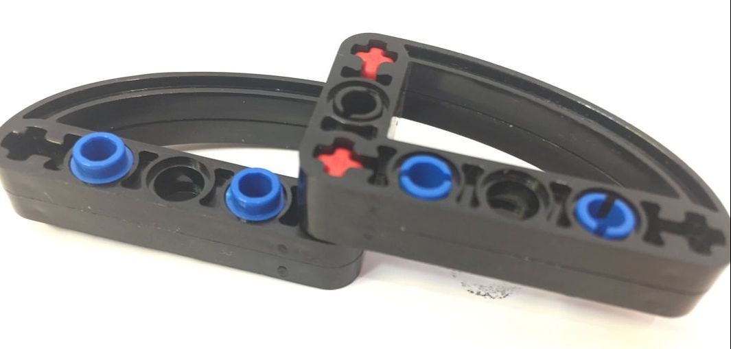
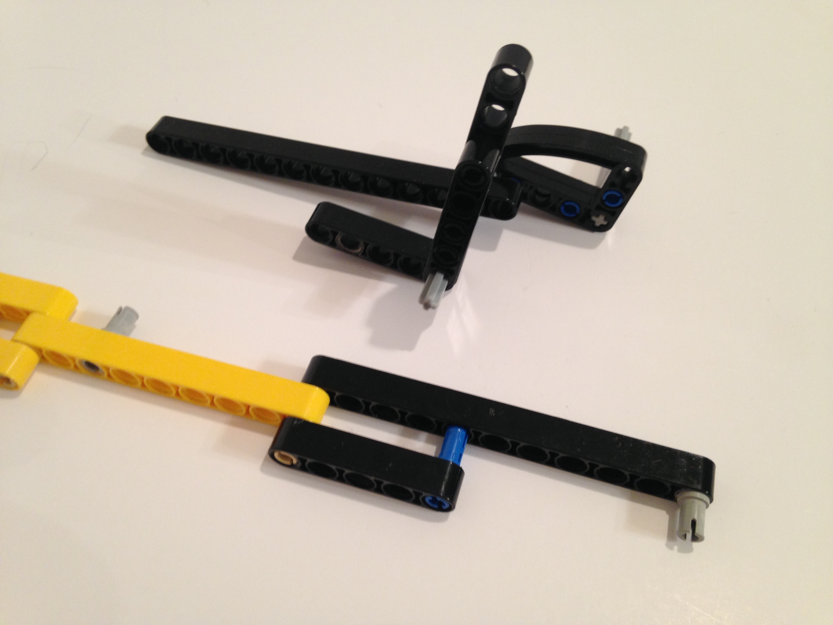
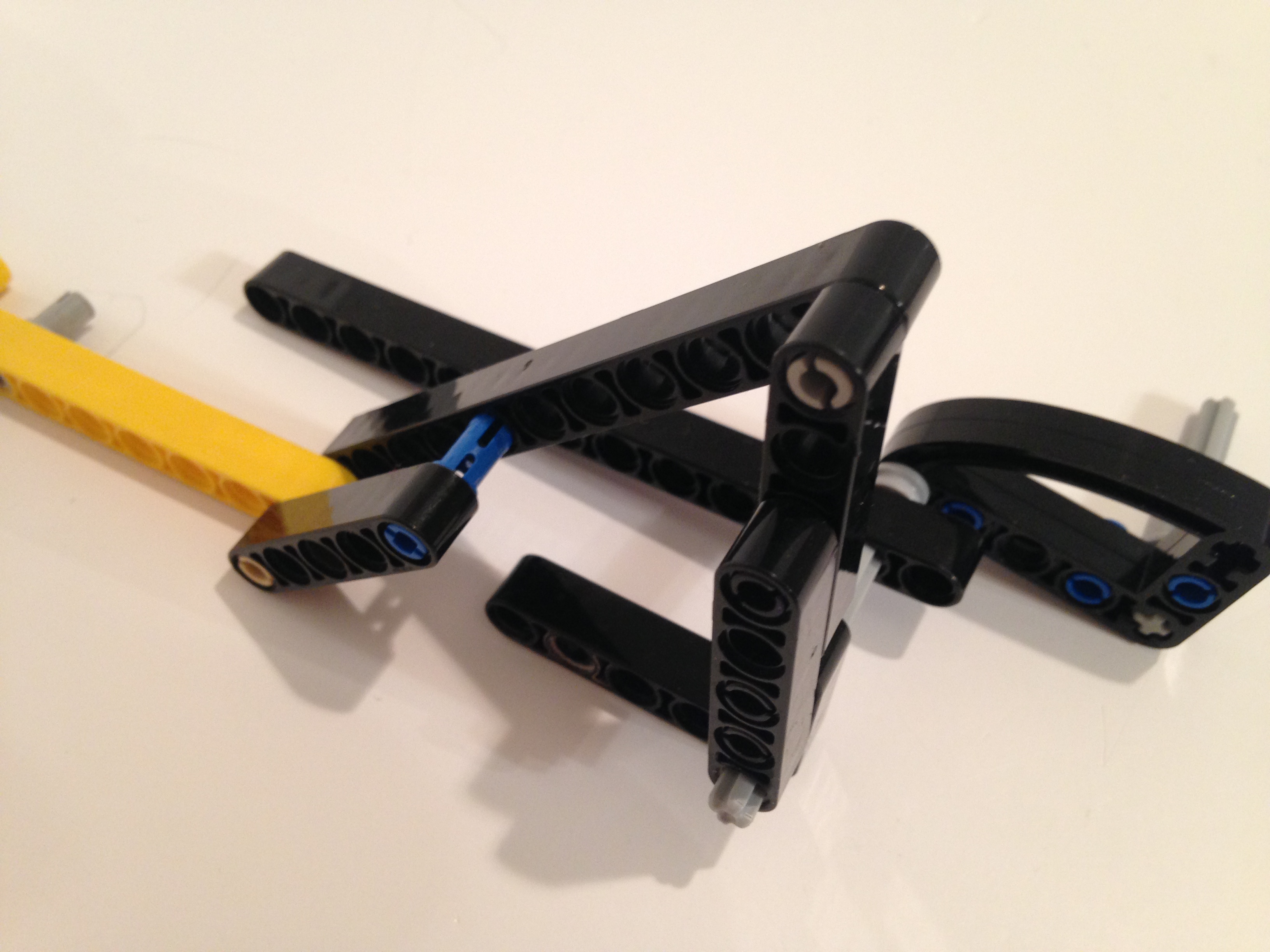
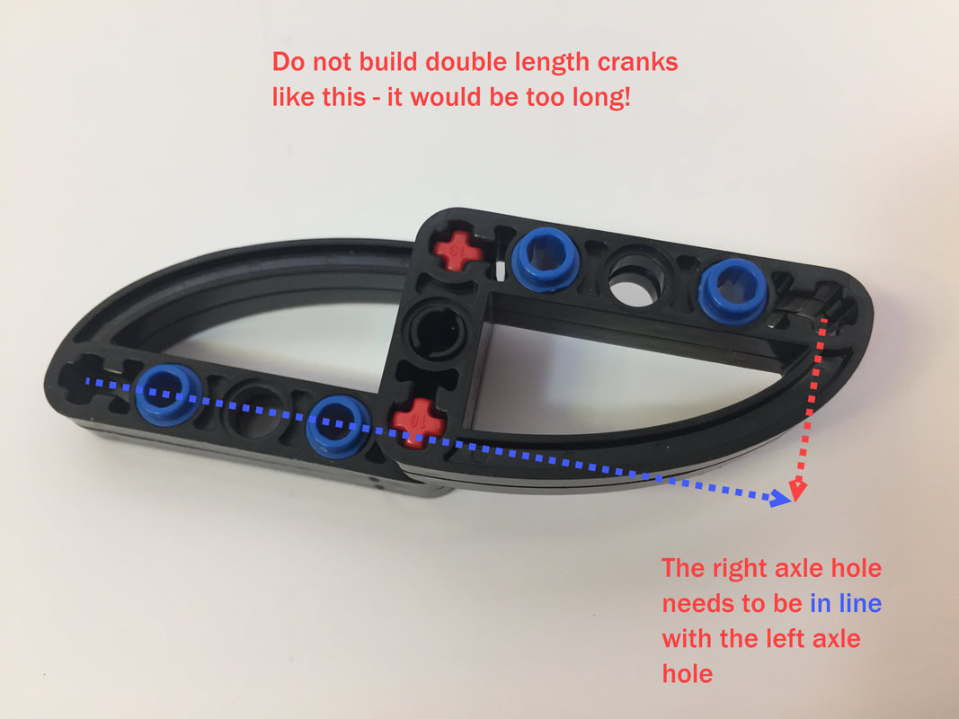
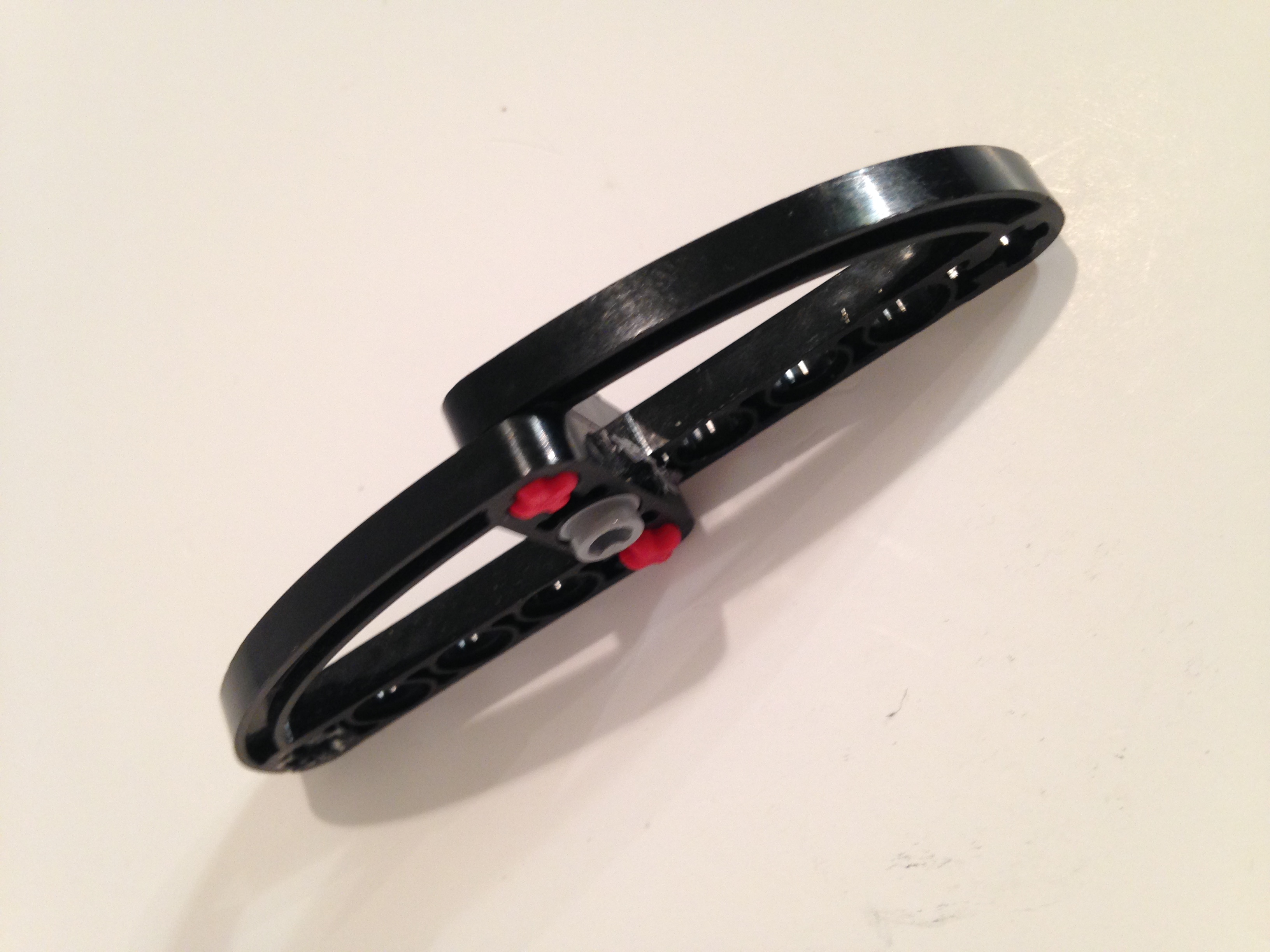
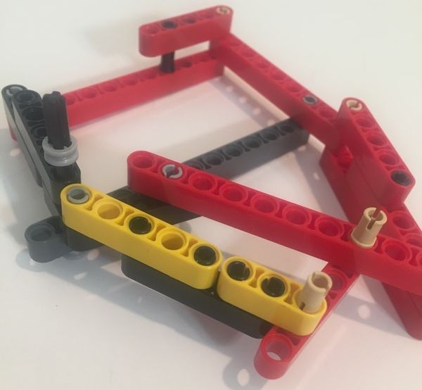
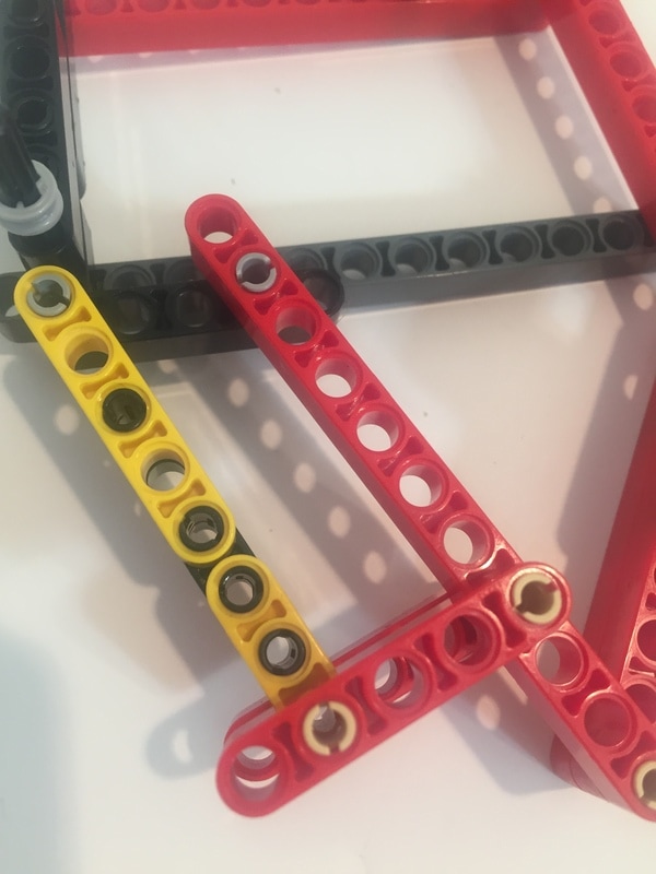
When building the double length cranks that link the inner and outer legs, make sure to build them with the axle holes in line as shown in the image below.
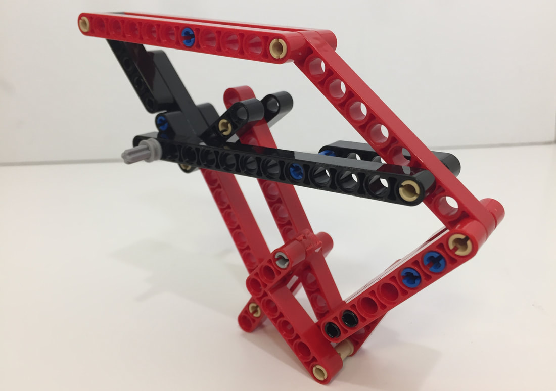
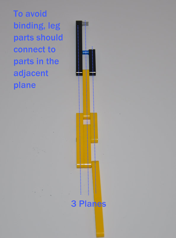
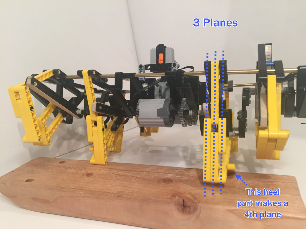
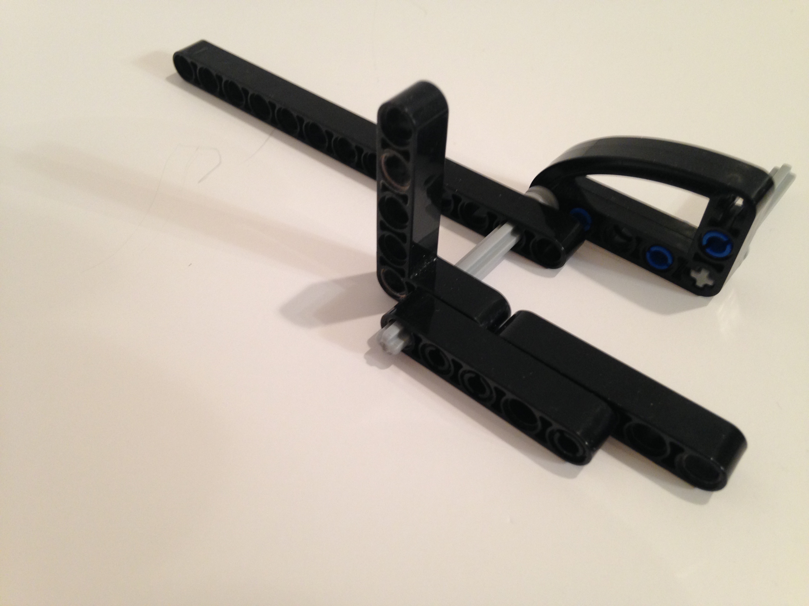
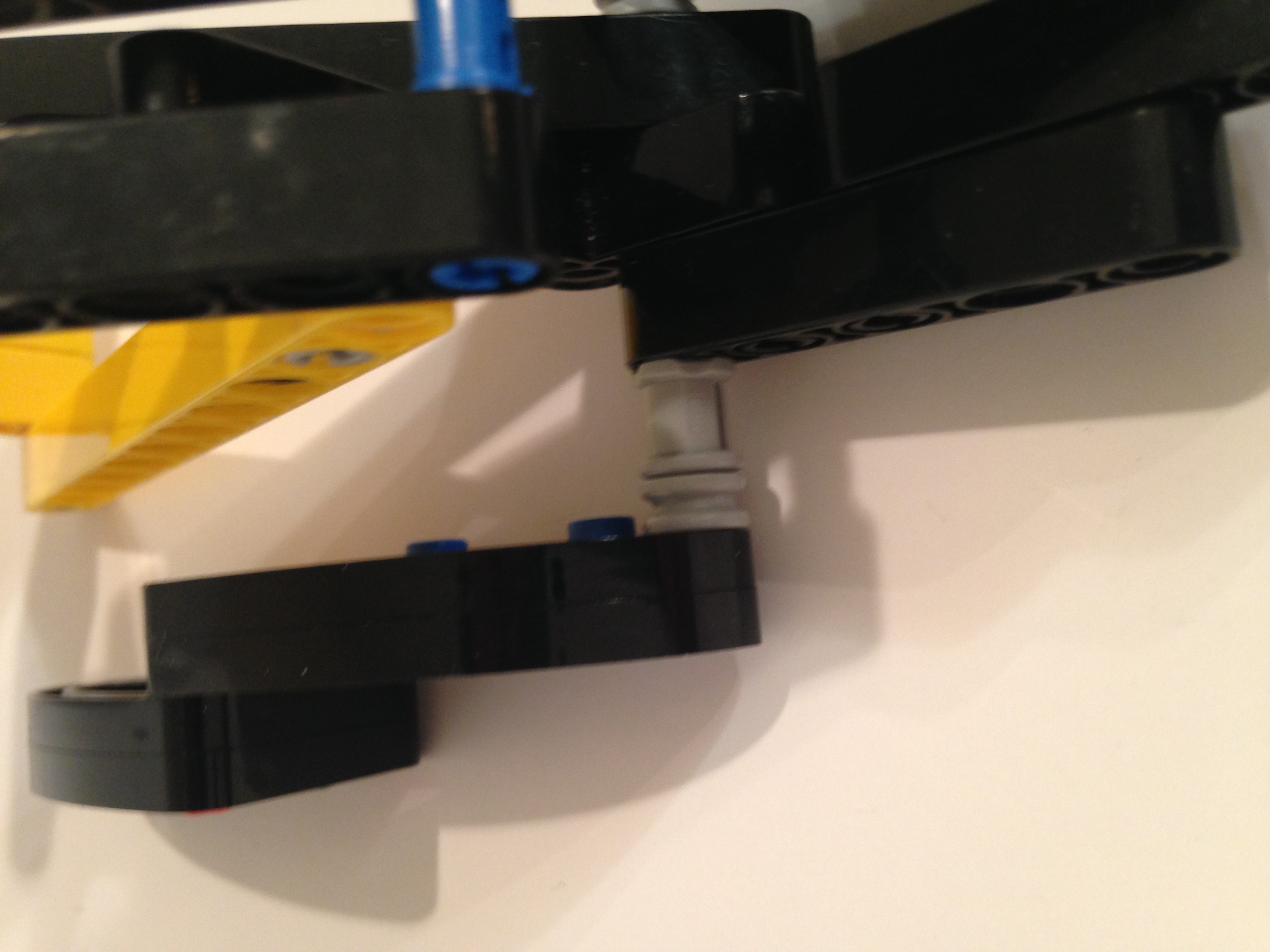
If leg parts aren't connected to parts in the adjacent plane the linkage can be twisted, which will cause the leg joints to bind. If your legs don't rotate easily, make sure your legs aren't twisted and that each part is in its correct plane as pictured below.
How to Build
Legs
General Comments:
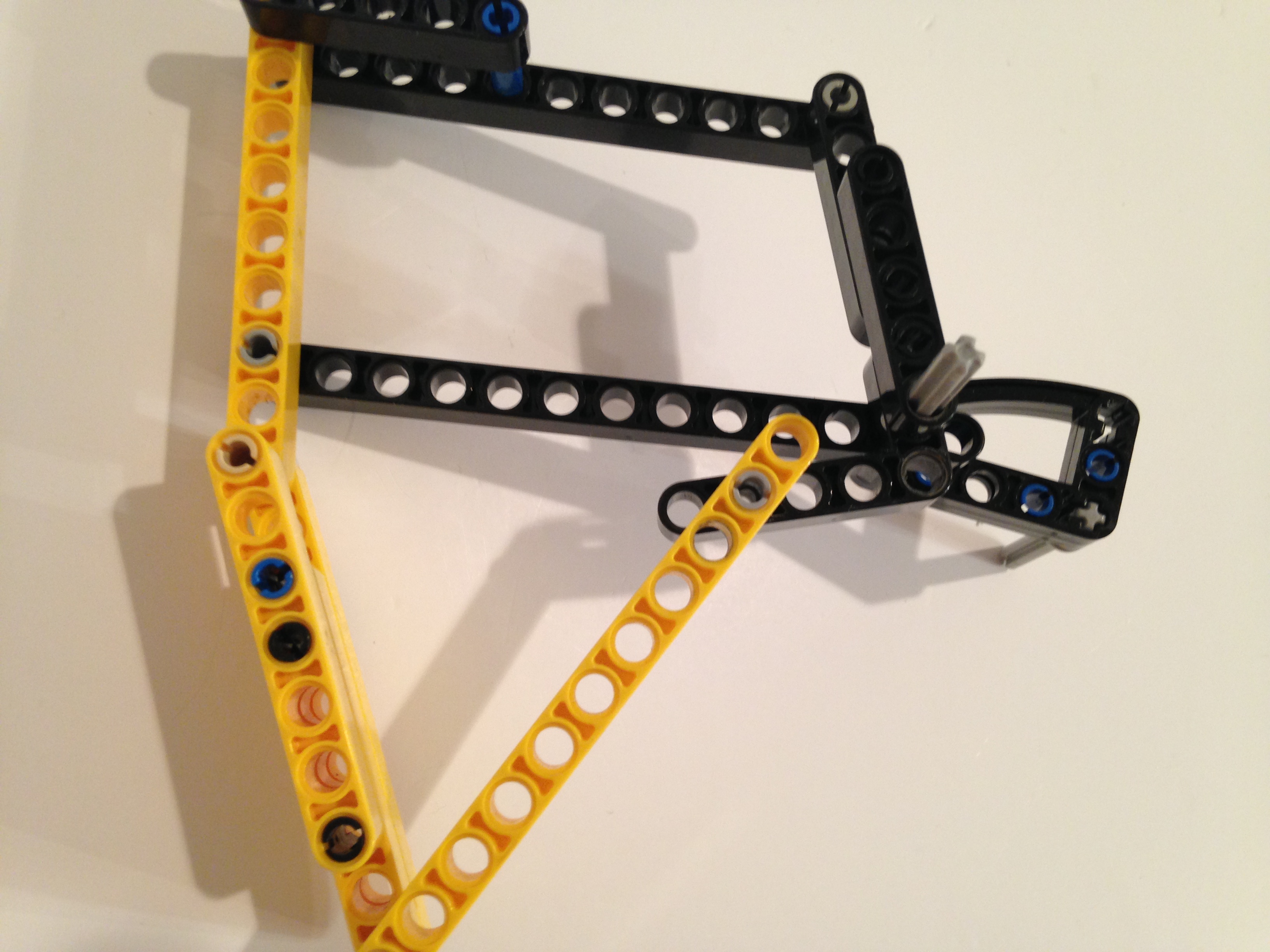
1. Engineers call these mechanical linkages "kinematic chains", so first I'll build each "link", or bar, of the leg's chain, and then connect the bars together at their joints.
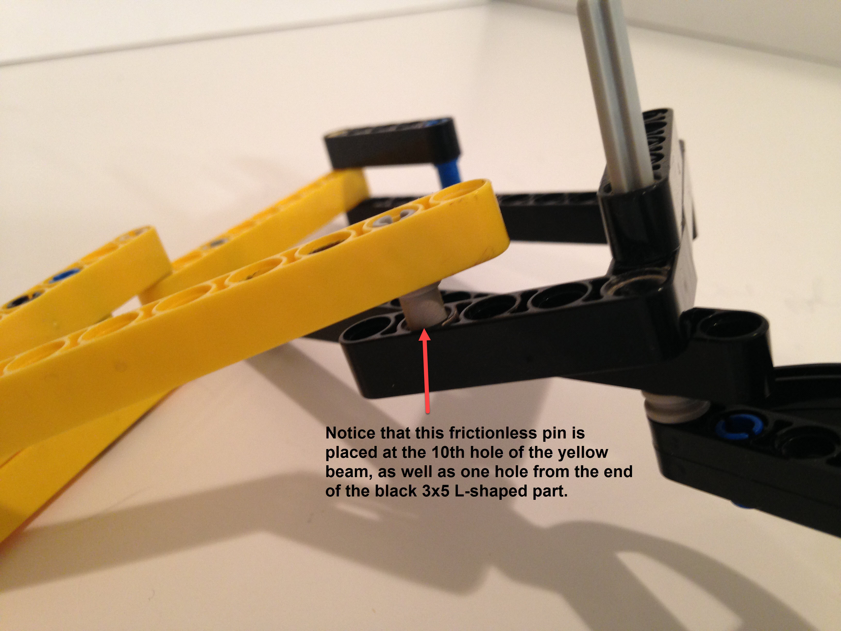
2. Be sure to use frictionless pins for movable joints!
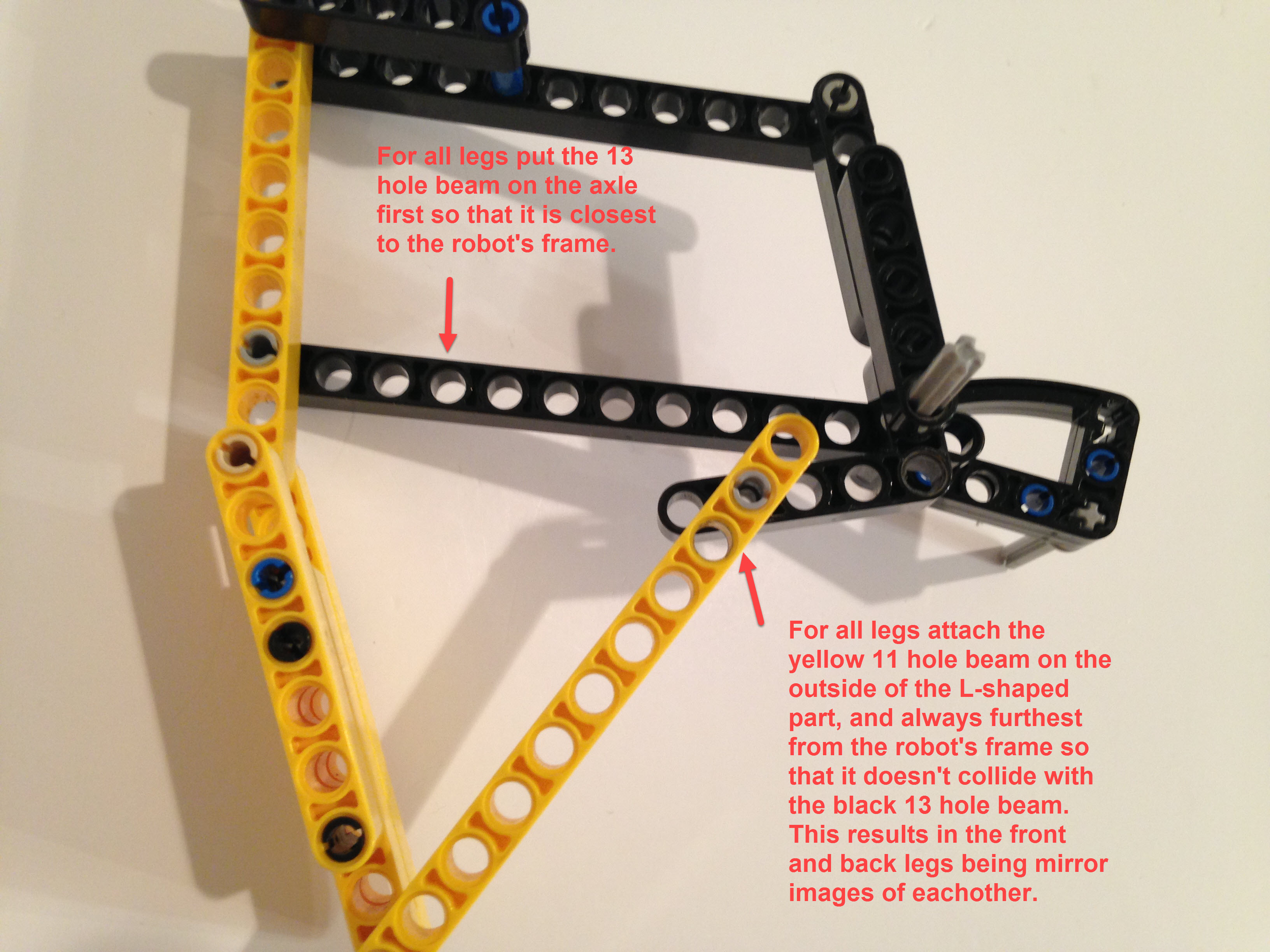
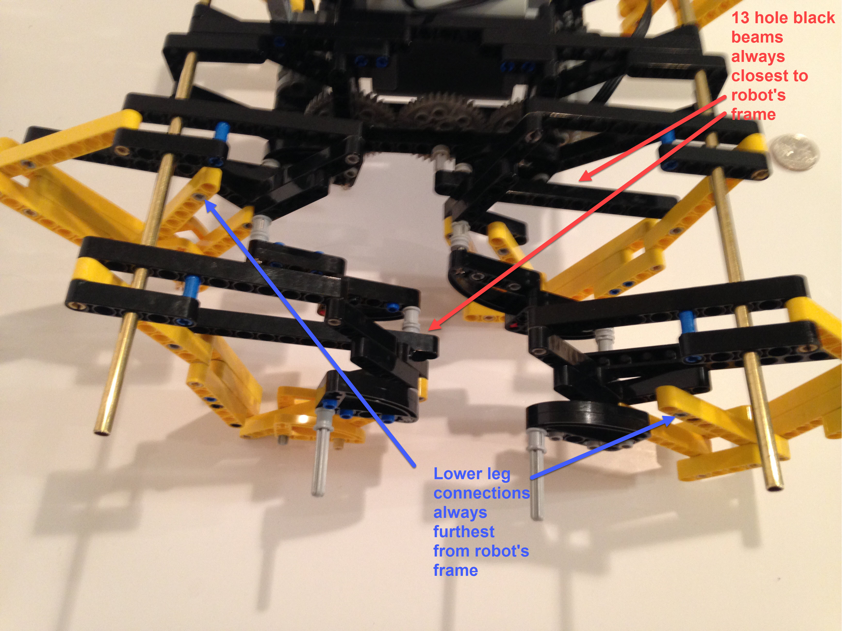
3. Take care to space each bar properly, with the bar's joint on the correct side, and with the use of bushings on axles as necessary. If the parts collide the linkage can lock up and gears will grind, and you will find it is much easier to get your leg spacing correct before assembling the entire walker than it is to fix the legs in a fully assembled walker! You will find details on how to properly space the leg parts later in these instructions.
UPDATE: The following instructions include some commentary on the reasons behind TrotBot's design (for those that are interested) , but are not in the format of professionally produced LEGO instructions. Fortunately, Catweazel has created professional computer-rendered instructions for building TrotBot in LEGO, a part list, and a convenient way to order them via his rebrickable page.
We will eventually get to TrotBot's linkage below...
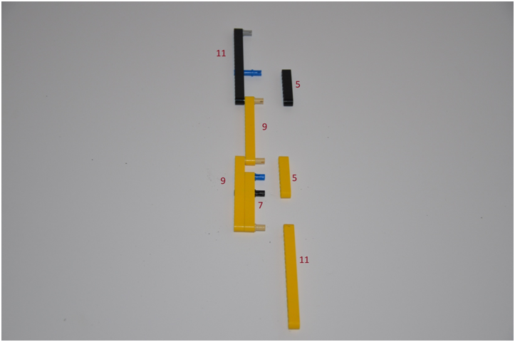
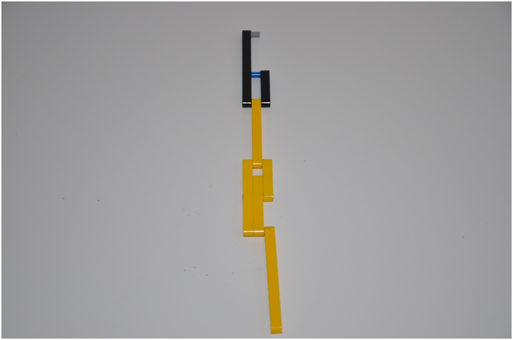
....but first we'll build each leg's "kinematic chain". The hole count of the beams is shown in red below. The yellow beam of length 5 on the right can also be of length 7, as it is in some of the later pictures.
Make 8 of the above leg chains.
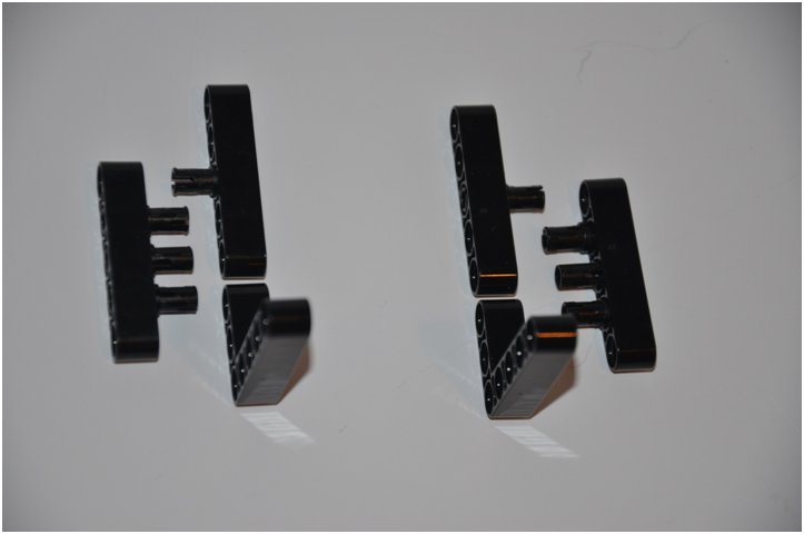
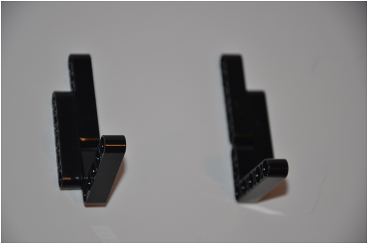
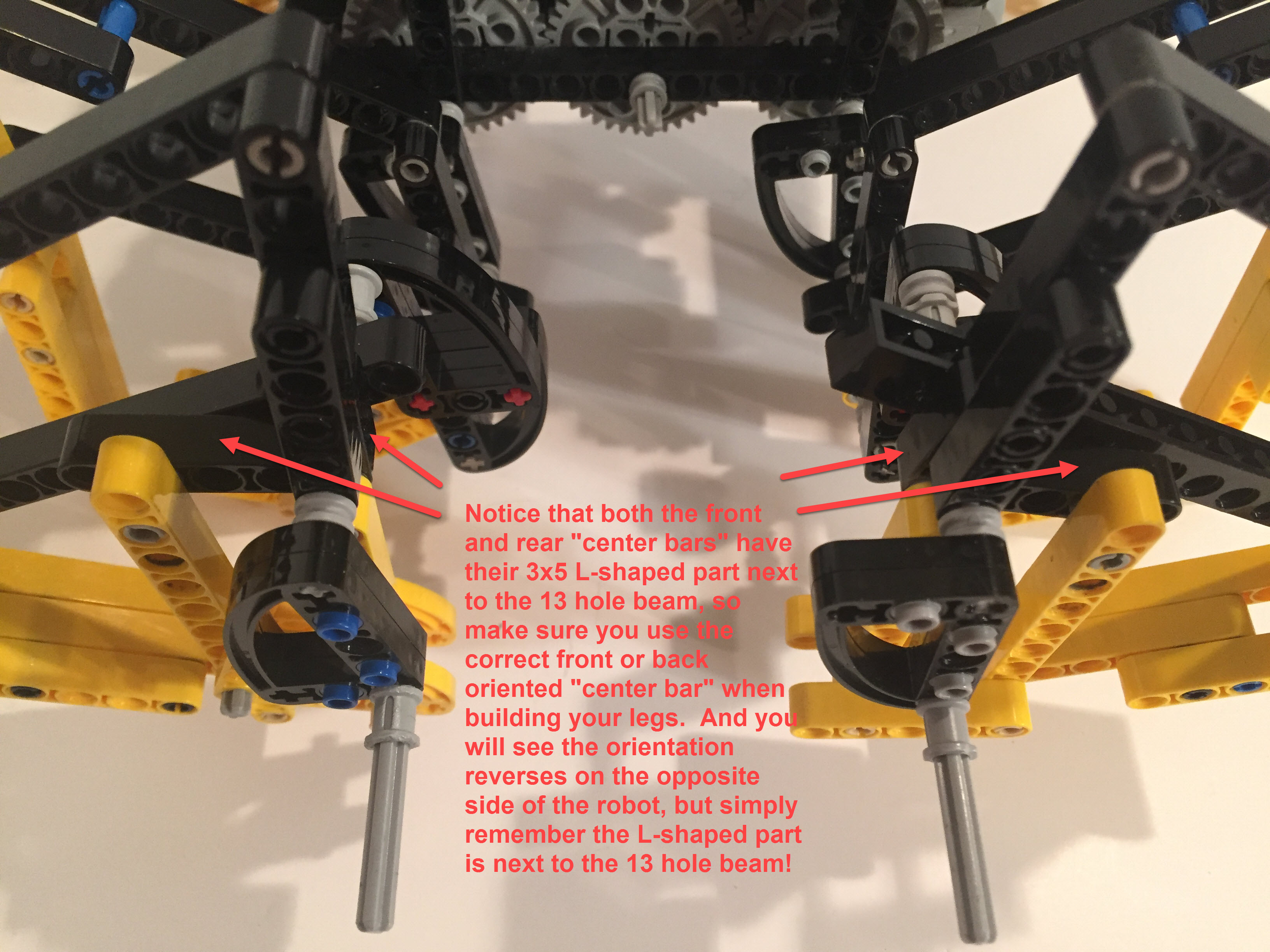
Below I build the chain's "center bar", which is the part that is rotated by the crank and has four joints linking to other bars. Notice that the two parts are mirror images of each other, which is because the finished front and rear legs will be mirror images of each other.
Make 8 total "center bars", 4 of each orientation.
Next, we'll build the axle + crank system to drive a leg and transfer the motor's torque. We'll need 8 of the following crank/axle systems, one for each leg.
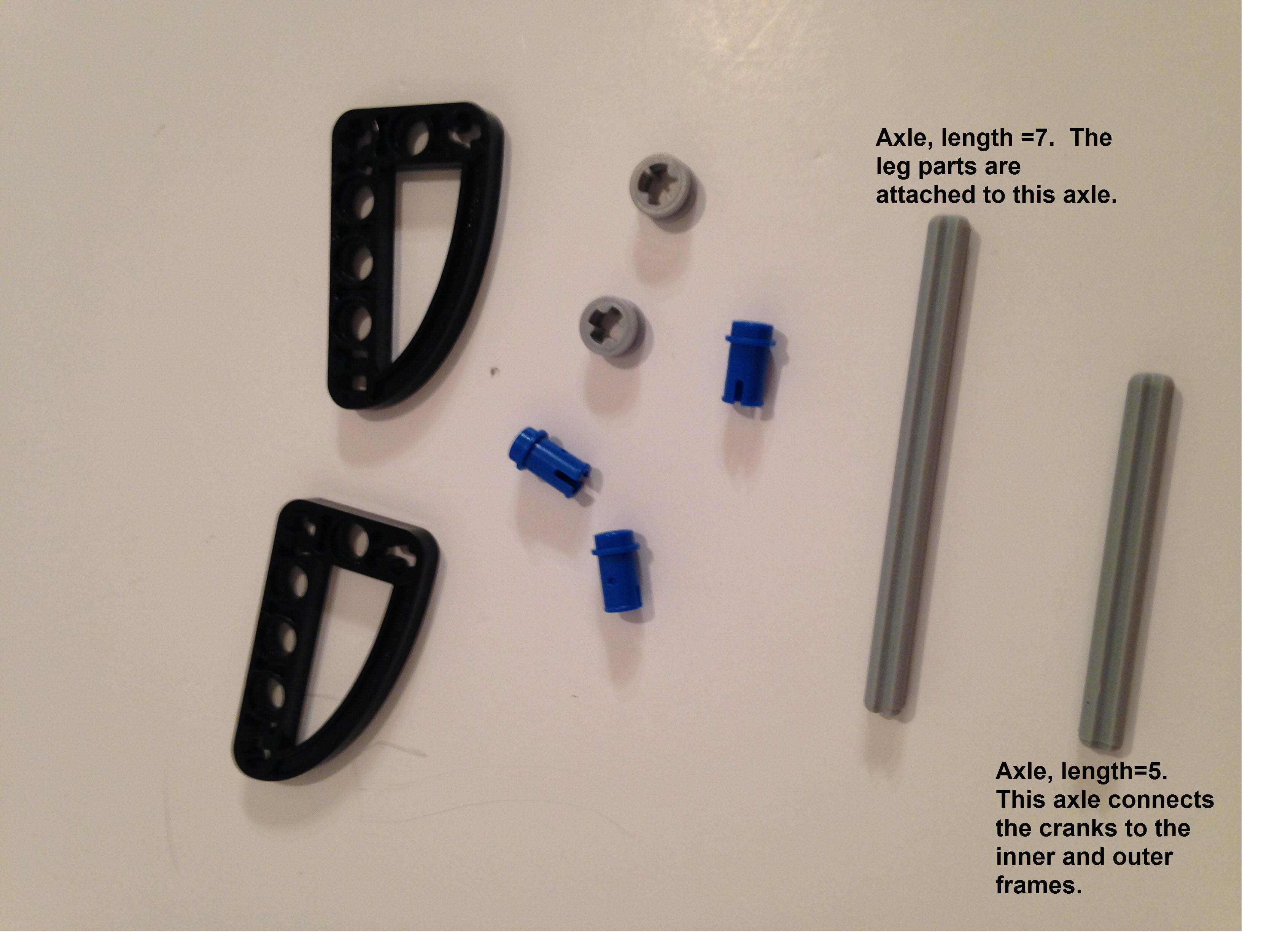
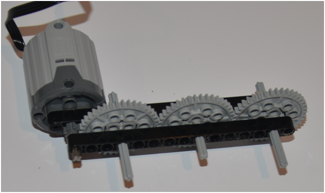
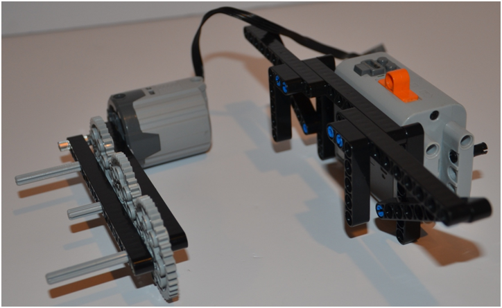
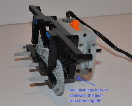
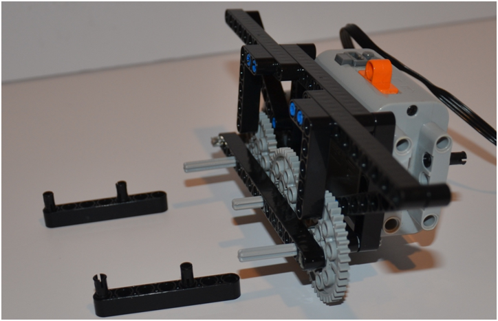
UPDATE: I switched the 4 inner frame axles from length 5 to 7 so that I could put a bushing on the inside of the frame to help sandwich the gear train in place.
UPDATE: I switched the 4 inner frame axles from length 5 to 7 so that I could put a bushing on the inside of the frame to help sandwich the gear train in place.
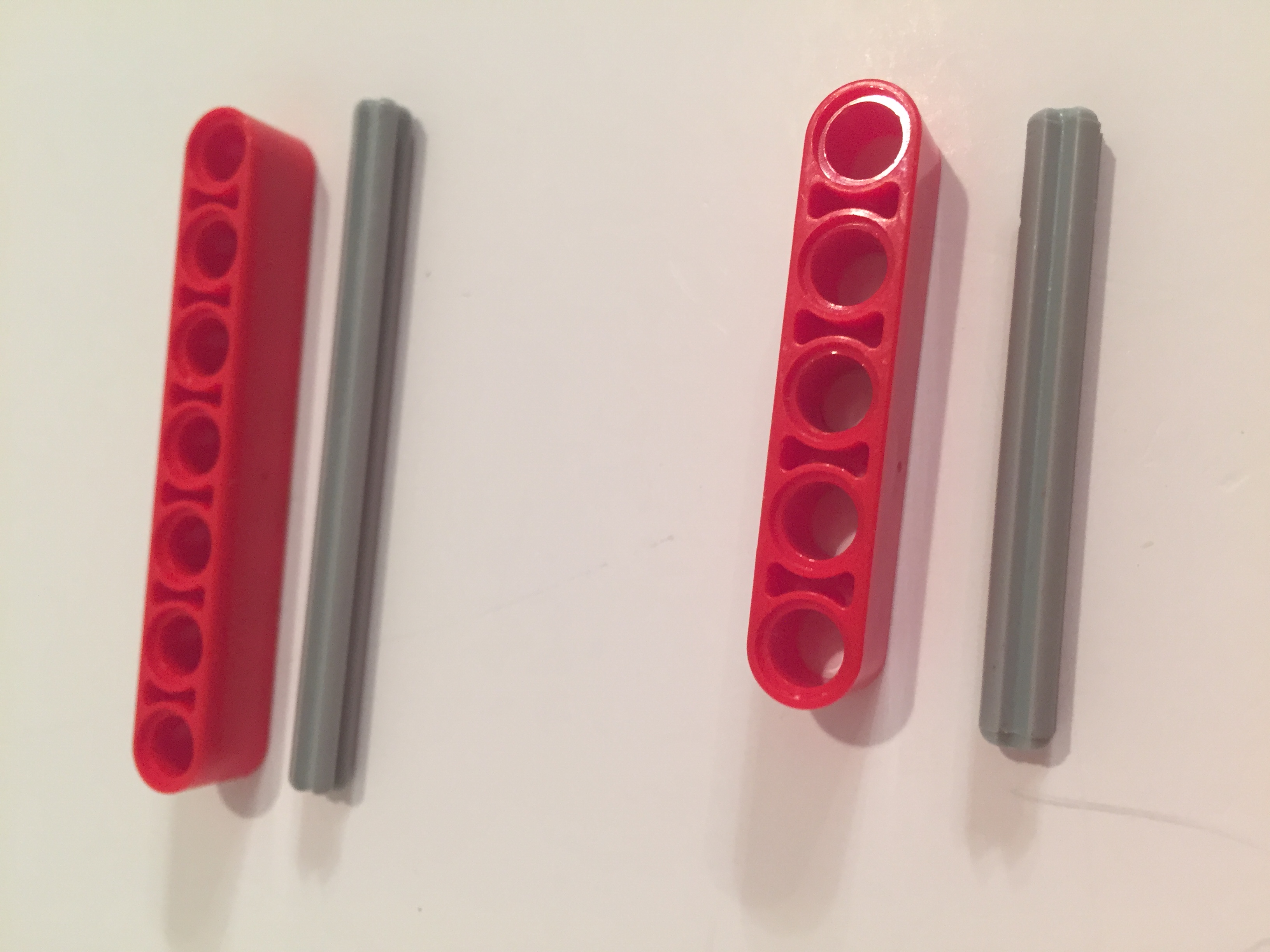
Below I paired the axles with beams with the same hole count to illustrate how LEGO references axle length.
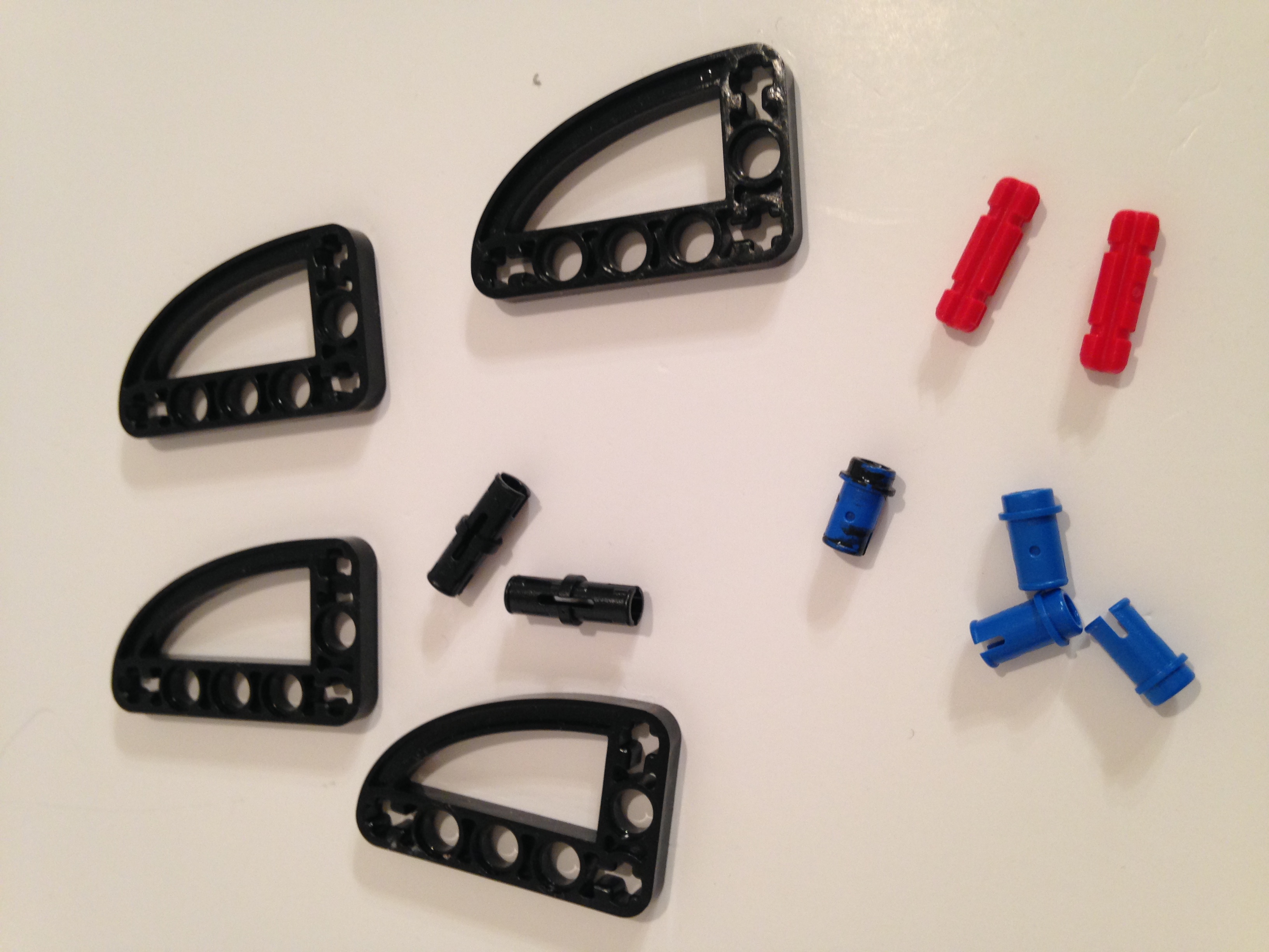
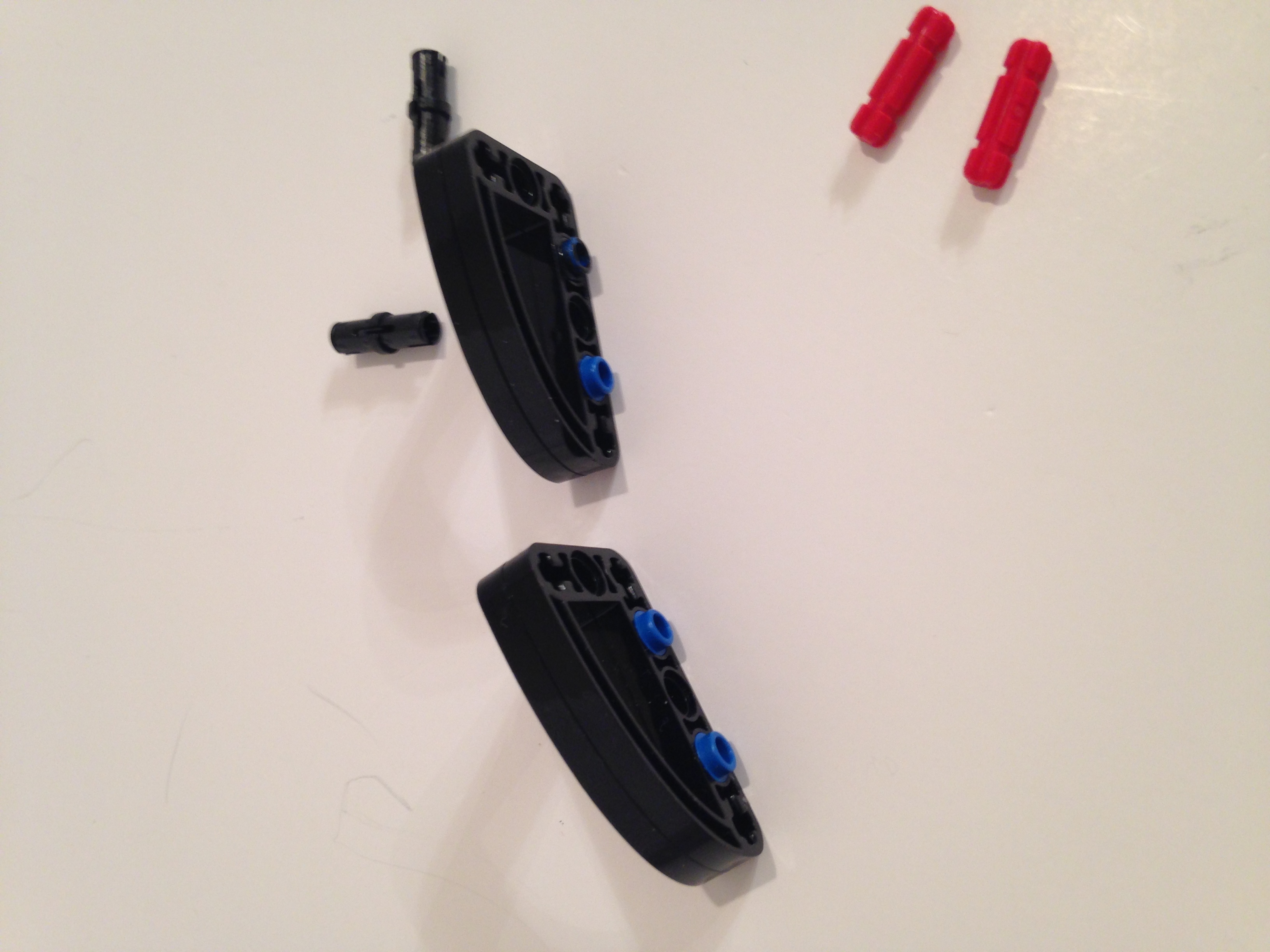
Because of the higher torque of walkers I connected two 3x5 cams together to make stronger cranks. Above is such a pair with an axle of length 5 for connection to the frame. UPDATE: I switched the 4 inner frame axles from length 5 to 7 so that I could put a bushing on the inside of the frame to help sandwich the gear train in place.
Attach the axle of length 7 on which the leg parts will be attached.
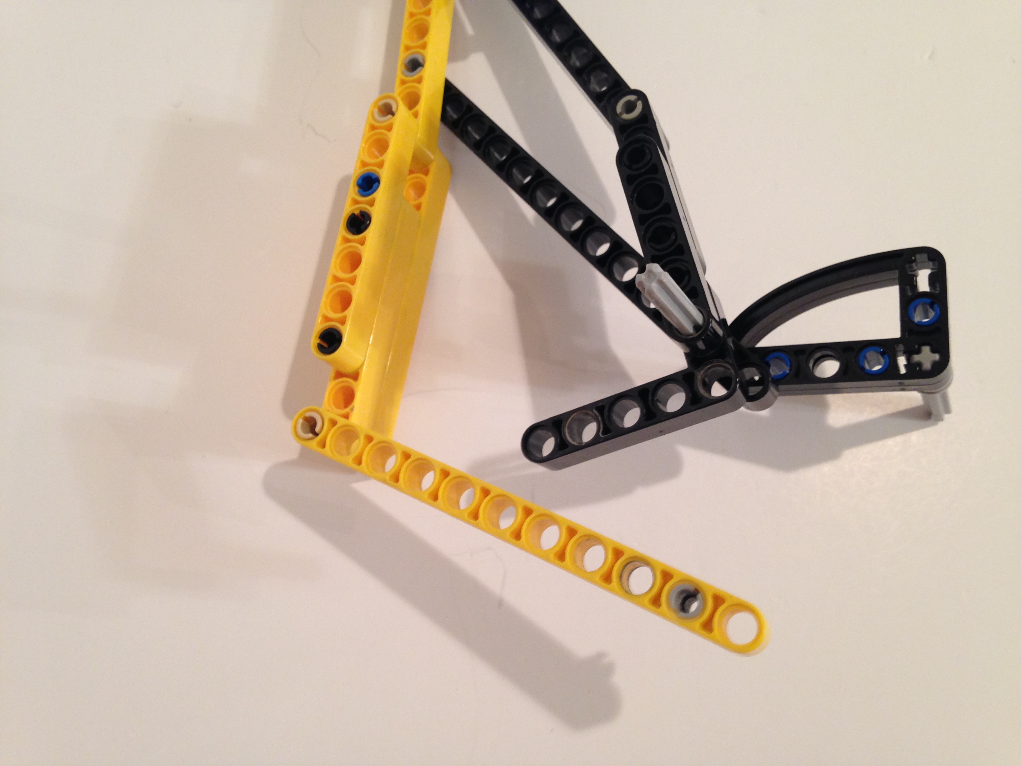
The bottom member of TrotBot's pantograph needs a beam with 12 holes, so I use a 13 hole beam and pass the axle through the 12th hole. This 13 hole beam should always be the first leg part put on the axle so that it is closer to the robot's frame than the other leg parts.
Pass this axle thru the center bar, one hole from the bottom
Attach the "shoulder" of the leg chain to the top of the center bar
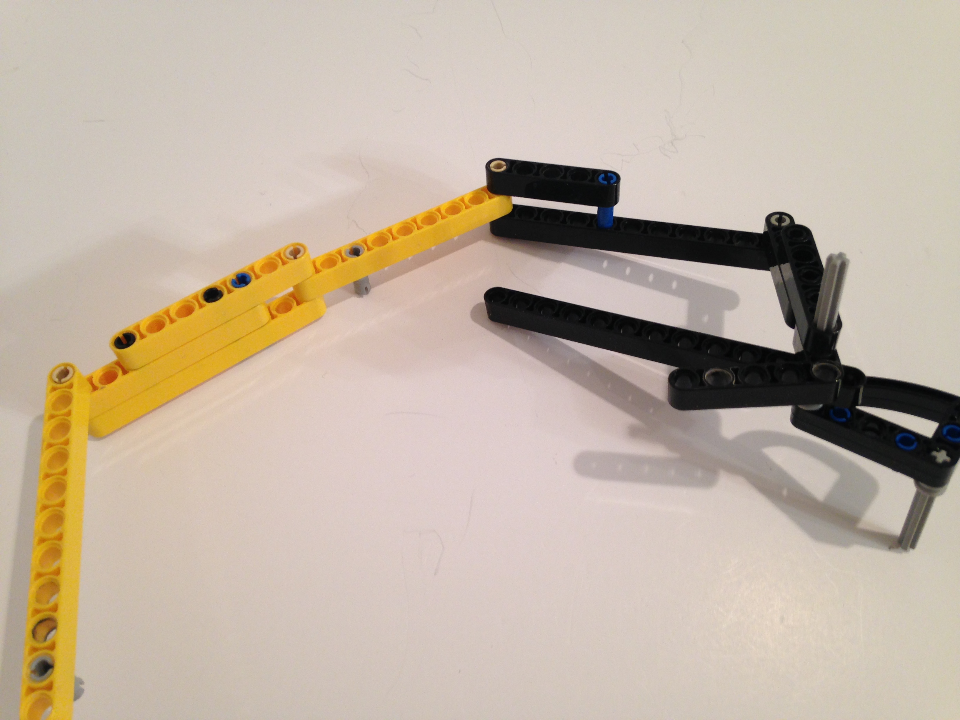
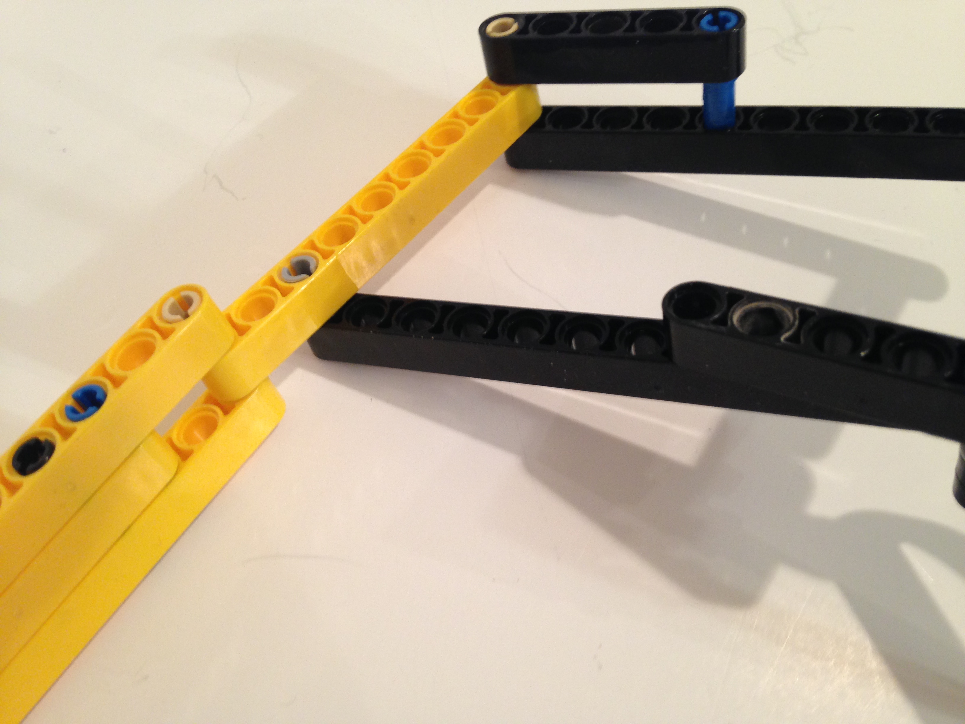
Fold the chain around to link the yellow sections to the black leg sections
Note: the following pics skip ahead to show the orientations of the leg parts when mounted on the robot's frame. We'll cover the building of the frame later in these instructions.
Spacing, Spacing, Spacing!
The trickiest part of building walker's linkages can be getting the spacing right between leg components. Too far, and the walker performs poorly. Too close, and leg parts collide when the motor runs. You may need to run a few experiments with your build to get your spacing just right, and the most useful LEGO part for controlling spacing on axles are bushings. Below are LEGO's half and full size bushings.
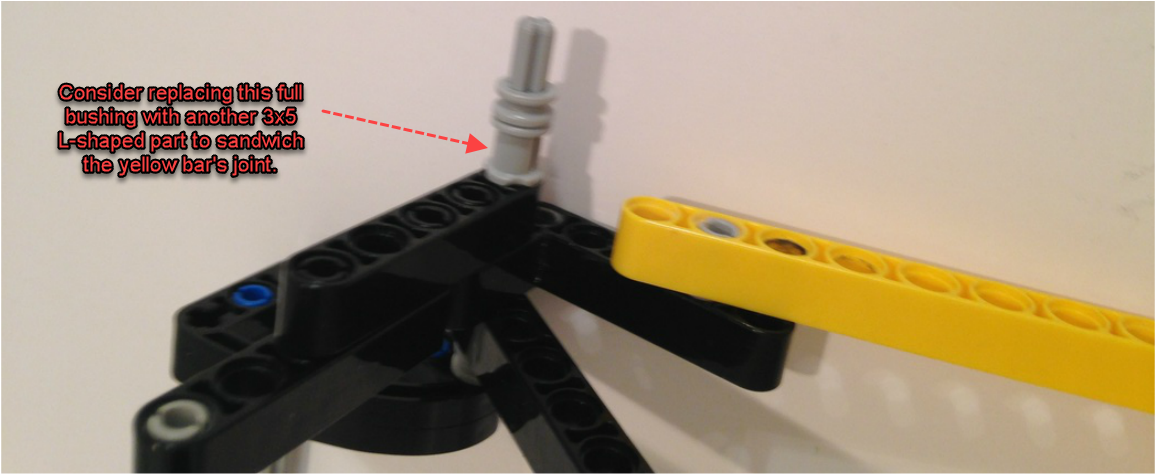
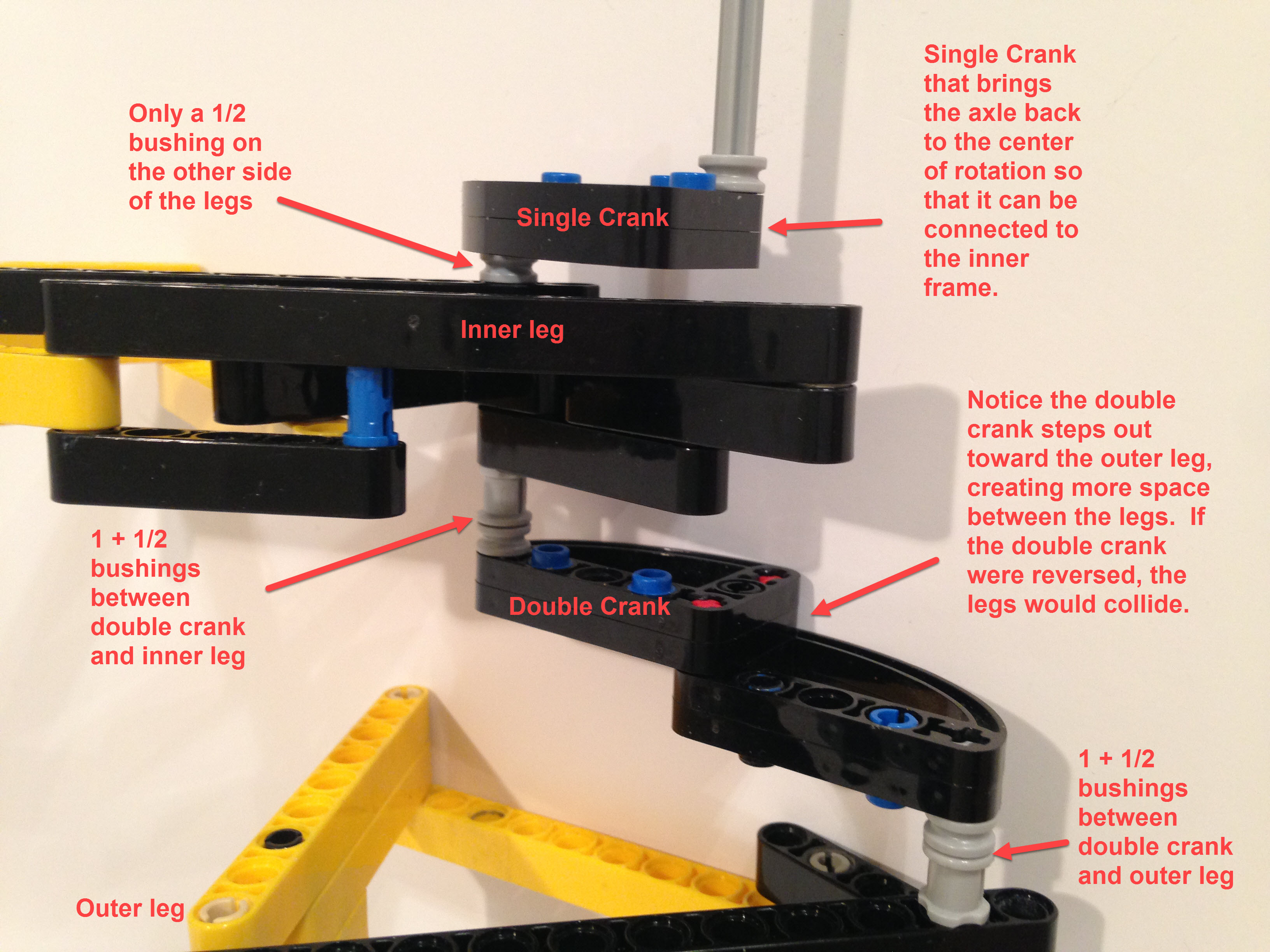
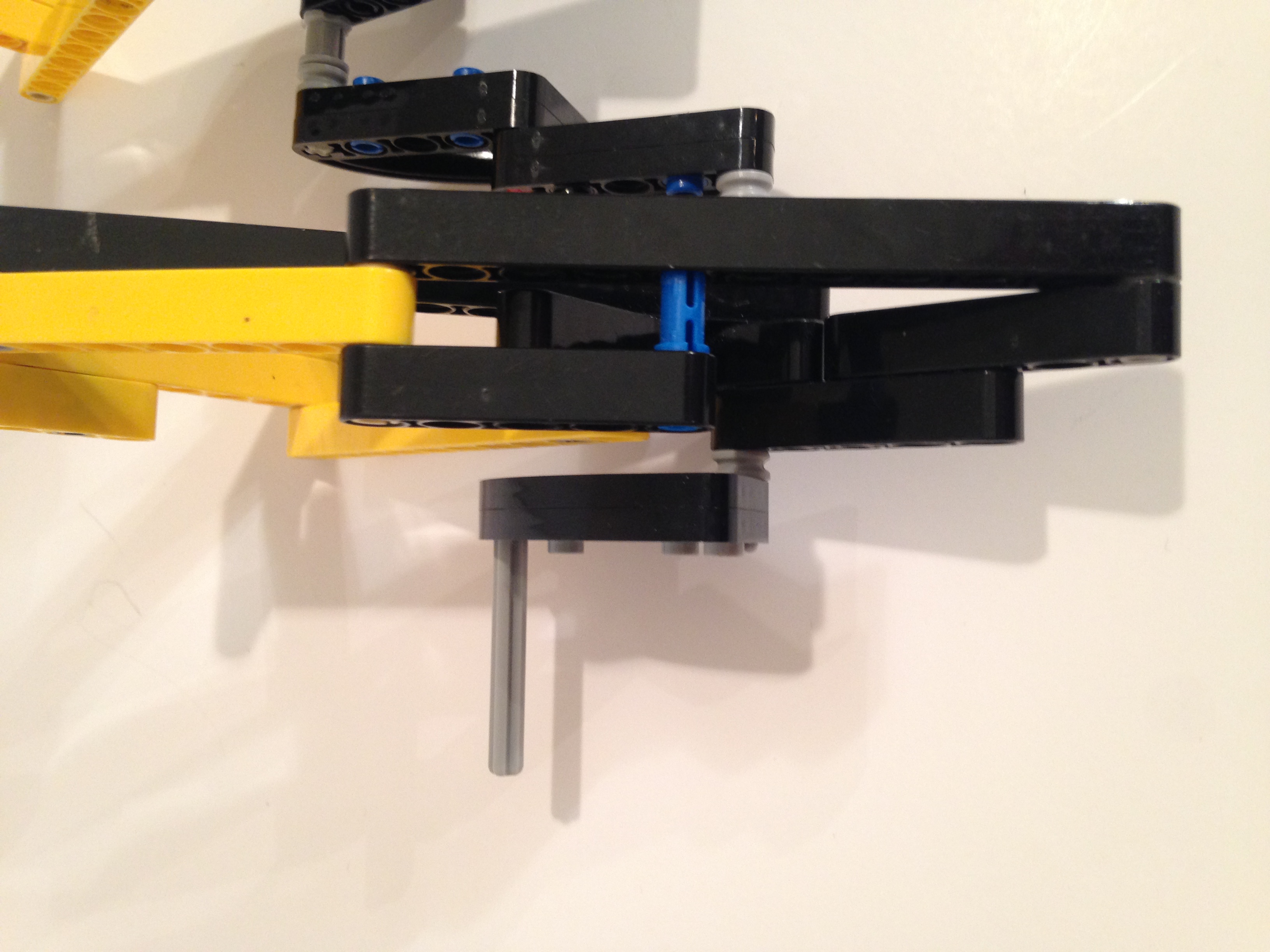
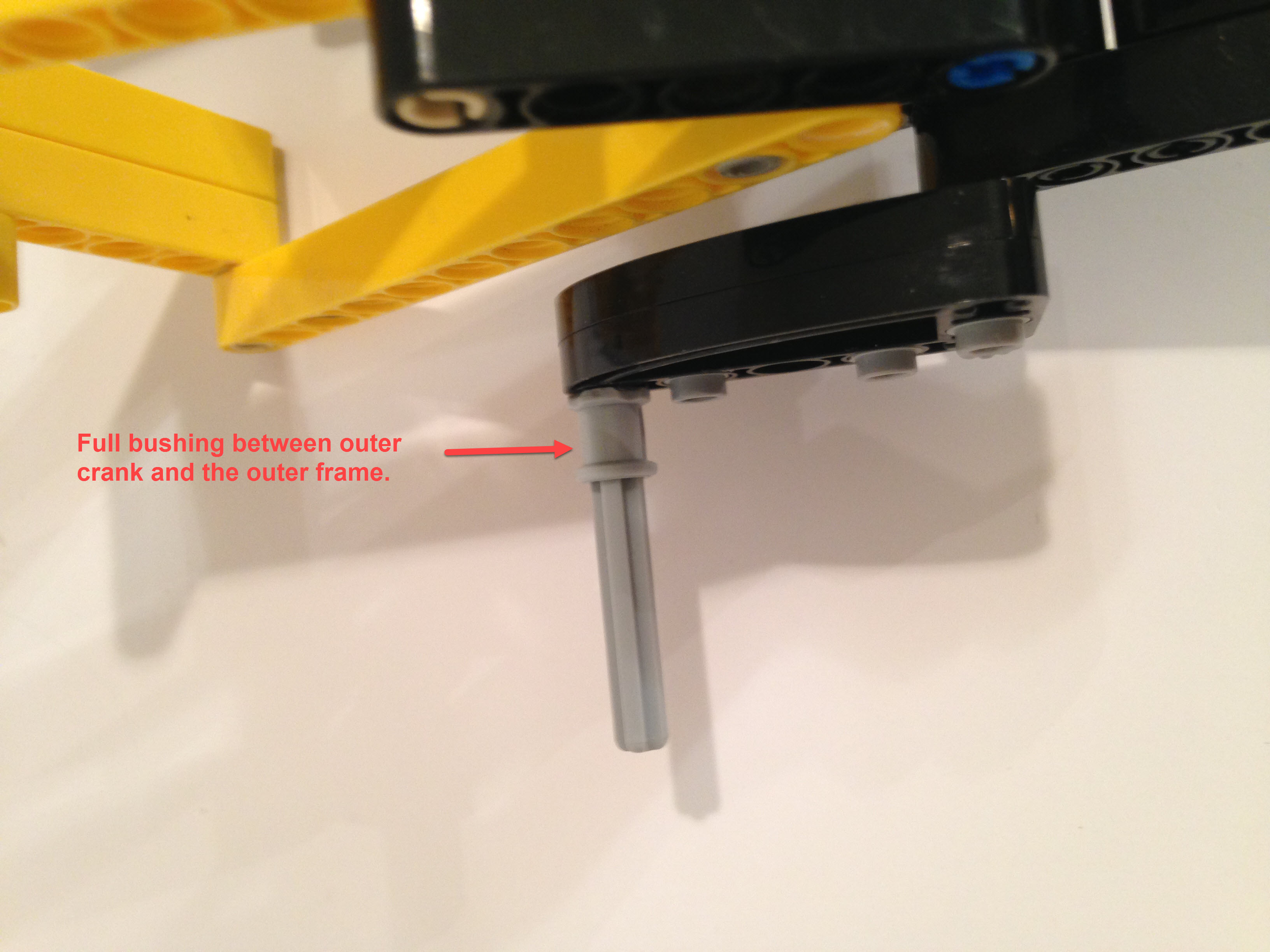
In this build the primary risk of leg parts colliding is the boundary between the inner and outer legs, therefore, below I add both a full and half bushing to the outer axle of this inner leg. This is shown in more detail after building the double-length crank.
Next, we need a crank to put the outer leg 180 degrees out of phase of the inner leg. We do this with a double-length crank oriented in the opposite direction of the inner crank. In other words, if the inner leg's crank is pointing at 3 o'clock , then the double-length crank should point at 9 o'clock.
Then build the outer leg in the same way and attach its axle to the double length crank:
Below is another build option for the double-length crank, but I found I had to use plastic modelers cement to make it strong enough, and it required adding more bushings to the axle to ensure the legs were space far enough apart. If you go with the below double-length crank be sure to add another 1/2 bushing between it and the inner and outer legs.
Next, add the outer crank which connects the transmission to the outer frame.
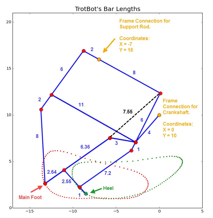
Next, add the "heel" portion of the "articulated foot". As you can see in the below schematic of our large-scale TrotBot, the heel strikes before the main foot, resulting in a smoother gait and lower power requirements. TrotBots without the heavy/wide EV3 brick can walk reasonably well without the heel, but the gait is bumpier and more torque is required by the motors, so I recommend including TrotBot's heel.
Another benefit of TrotBot's heel is it steps higher on the backside of the foot-path, allowing TrotBot's rear legs to step about as high as the front legs to avoid getting stuck astride obstacles, as can be seen in this heel-path simulation:
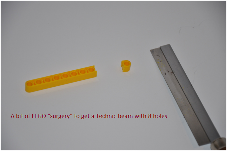
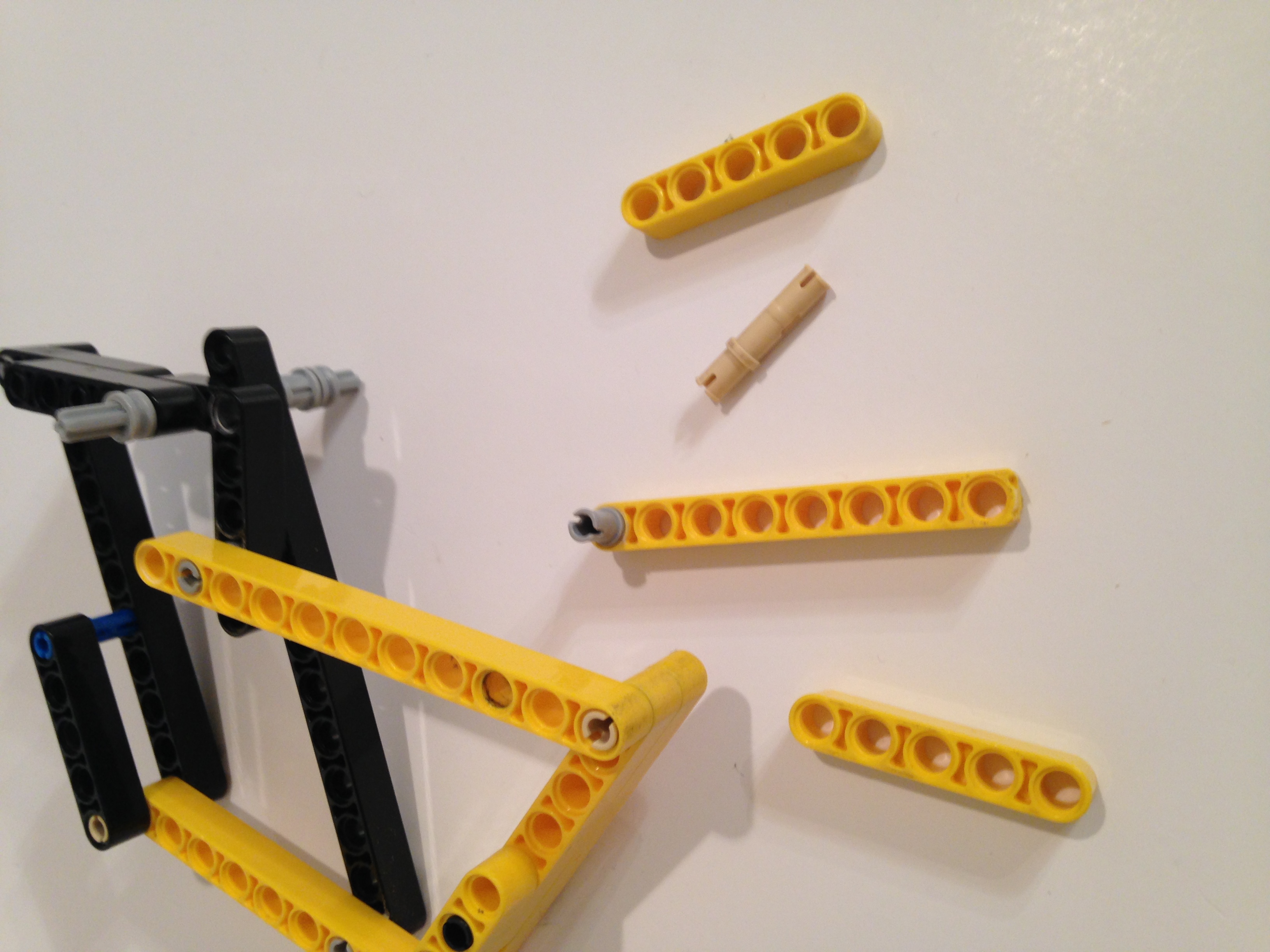
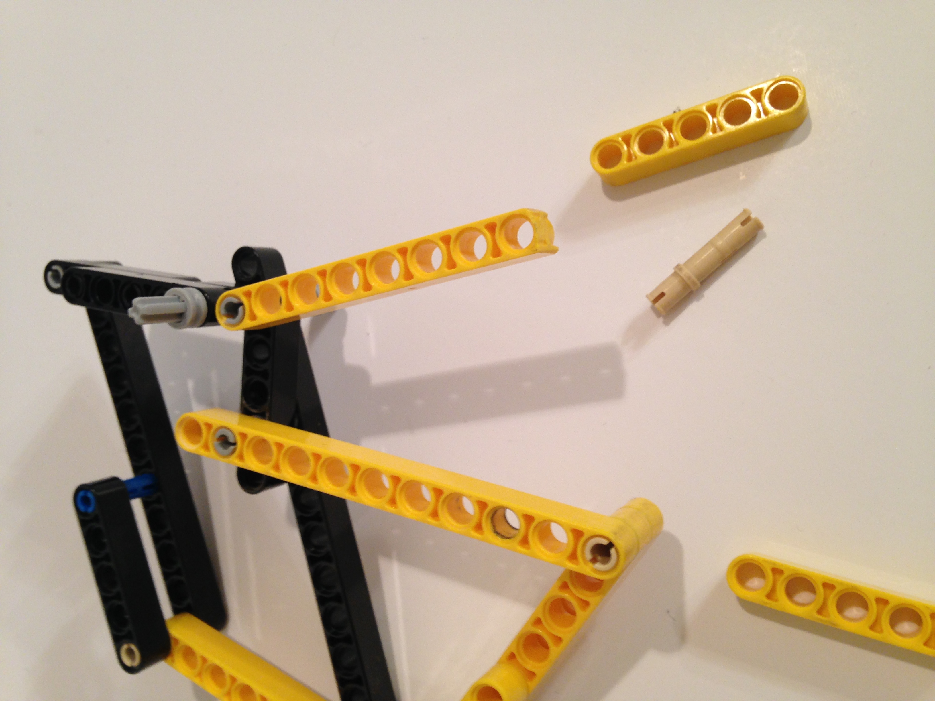
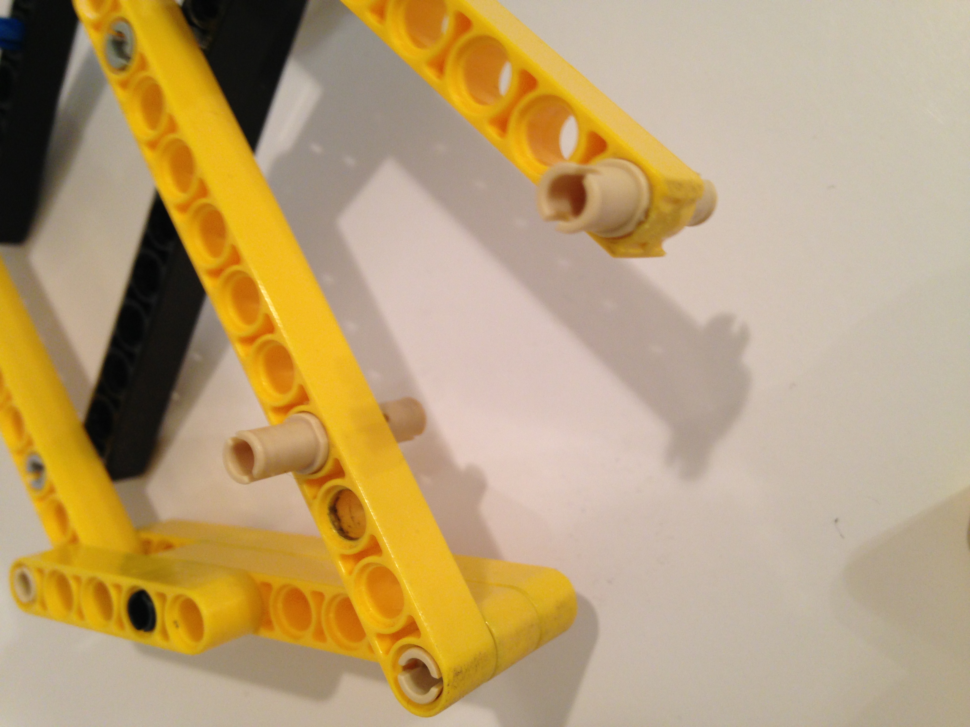
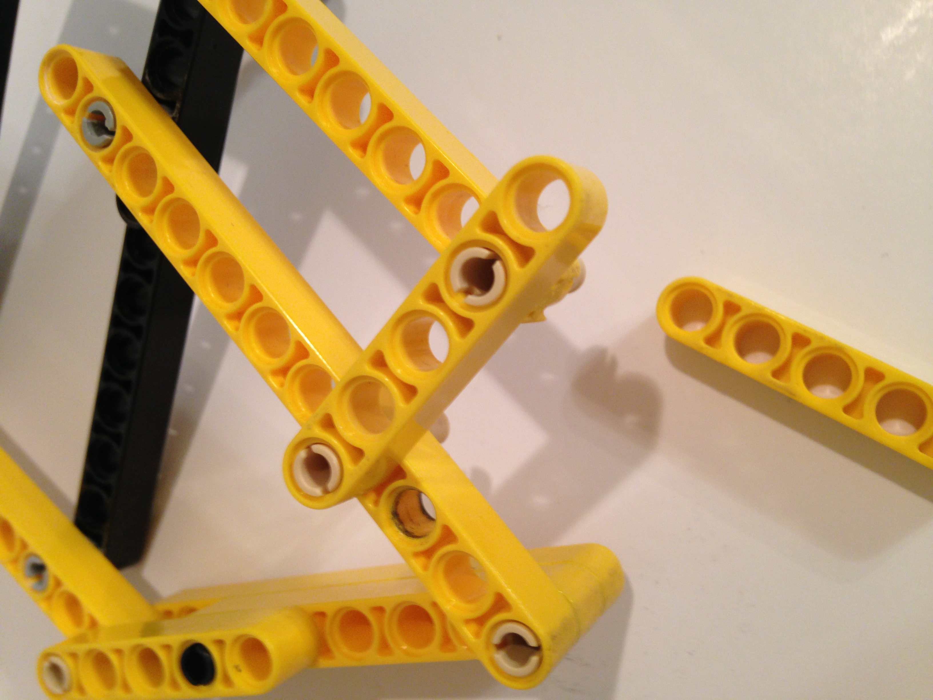
Notice that the beam that connects to the bottom of the center bar is only 8 holes in length. You can cut off one hole from a 9 hole beam as I did below (using a hobby saw), or you can build up an 8 hole beam from shorter parts, but you will need to be sure that such building up does not result in a wide part that causes the linkages to collide when the motor runs.
NOTE: If you don't want to cut your LEGO beams two examples of 8 hole beams made with shorter parts can be seen of few pics down.
You can also use the below cam part for the heel.
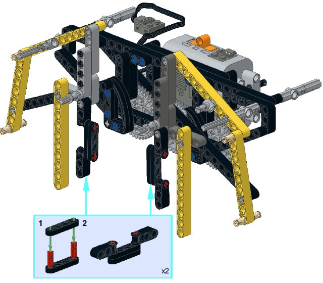
If you don't want to saw parts for the heel then below is Catweazel's idea for an 8 hole beam.
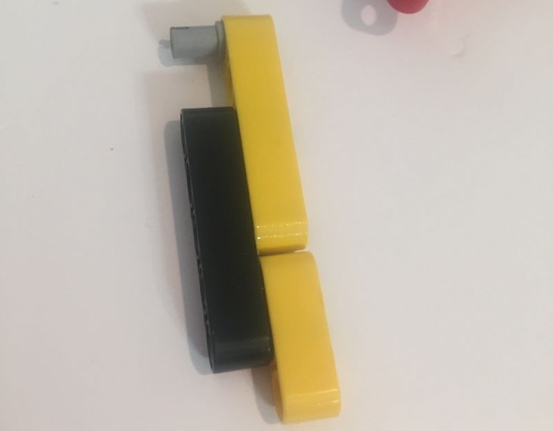
And below is another idea, but the black beam squeezes against the red beam a bit:
Make sure the 5 hole black beam is on the inside of the leg (or downside in these pics) so that it doesn't collide with the crank.
Frame
General Comments:
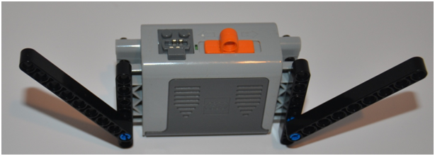
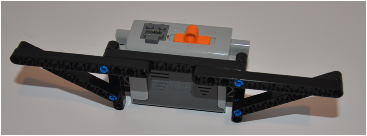
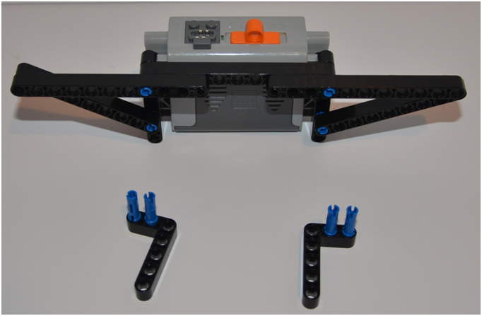
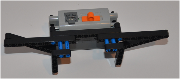
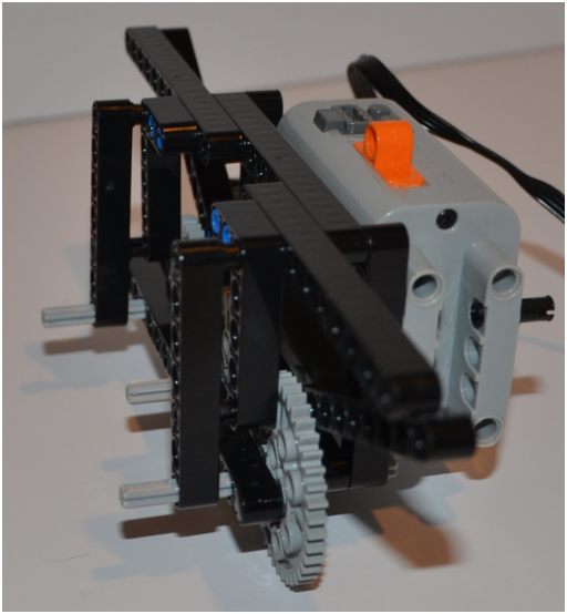
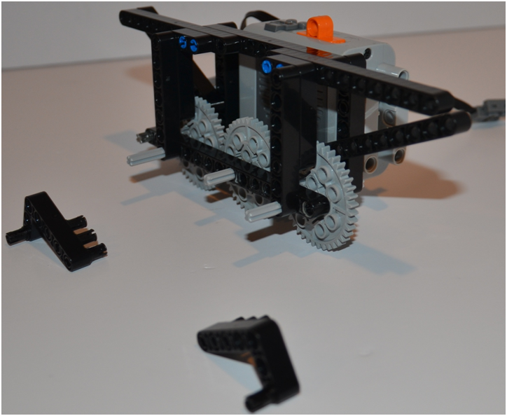
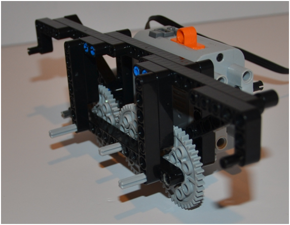
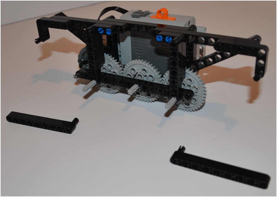
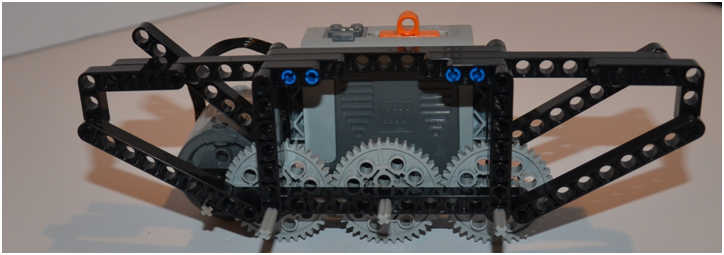
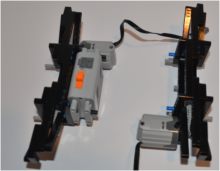
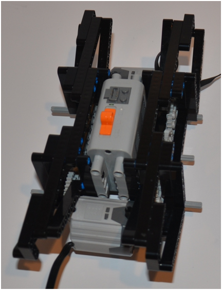
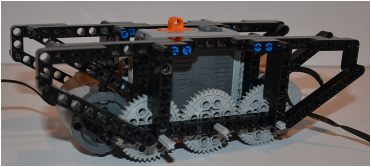
1. When possible, try to take advantage of the strength of the battery box, and connect frame parts to it.
2. Low center of gravity is always important for improving a vehicle's handling, and this is especially true for Walkers. Therefore, try to mount your battery boxes and motors as low in the frame as is feasible. Also, try to center your batteries and motors as close to the center of the walker as possible (not too far in front and back, nor side to side).
3. Strive to utilize triangles to make lighter/stronger frames since Walkers stress frames more than wheeled vehicles, especially when walking on bumpy ground.
UPDATE: To improve how TrotBot handles and climbs I recommend mounting the battery lower than is shown in the following pictures. It's a simple change where you replace the below 7-hole beams with 11-hole beams, which I show how to do in this blog post.
You can use either LEGO's 8883 medium motors for a faster TrotBot, or, if you want TrotBot to handle rougher terrain like this, then use LEGO's half-speed, 4x torque XL 8882 motors as pictured below.
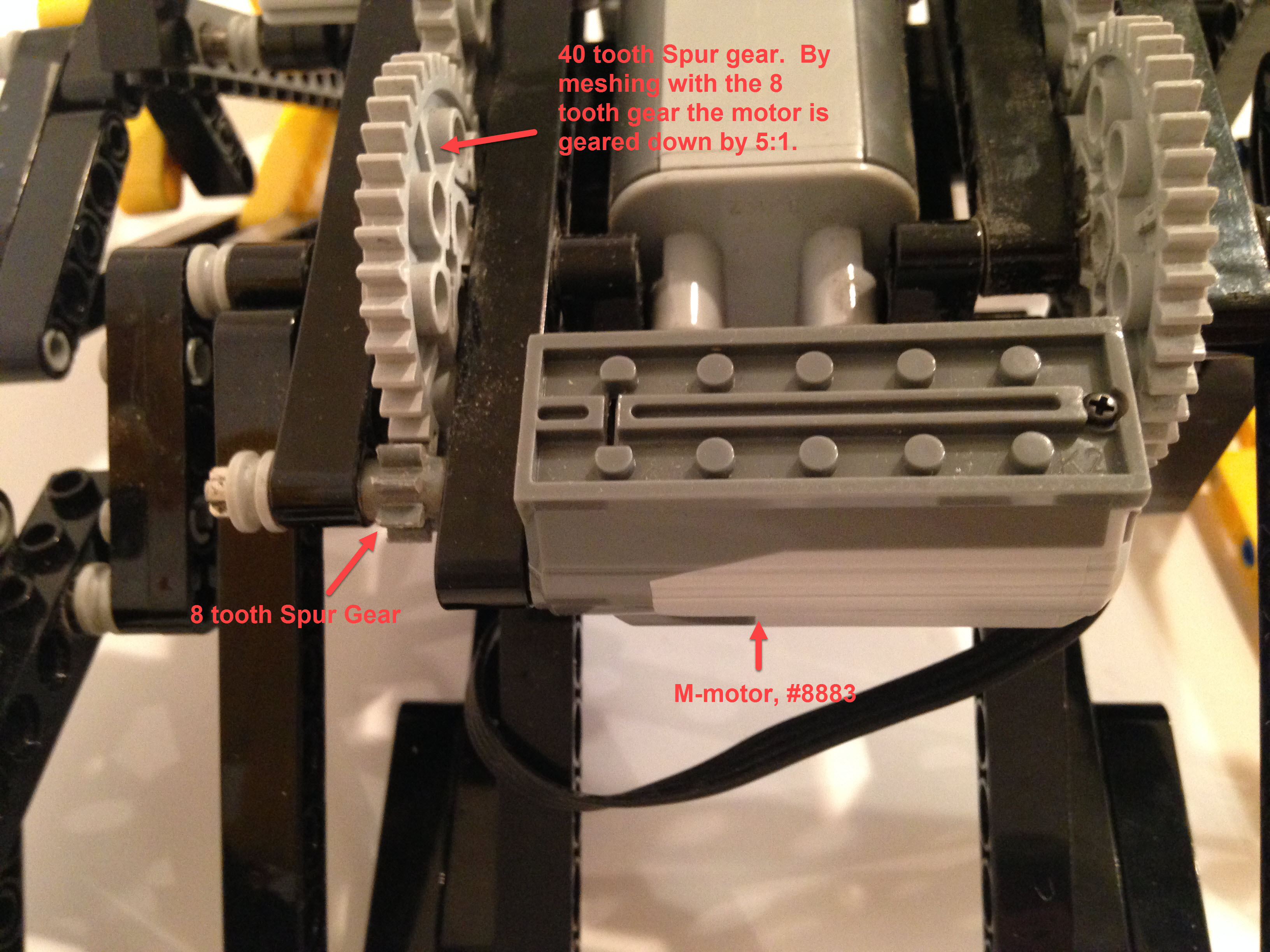
To show the difference between XL and M-motors, below is a pic of an M-motor mounted, taken from the underside of this build
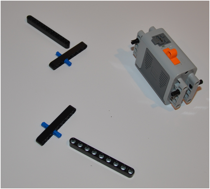
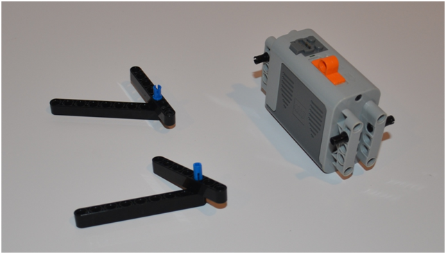
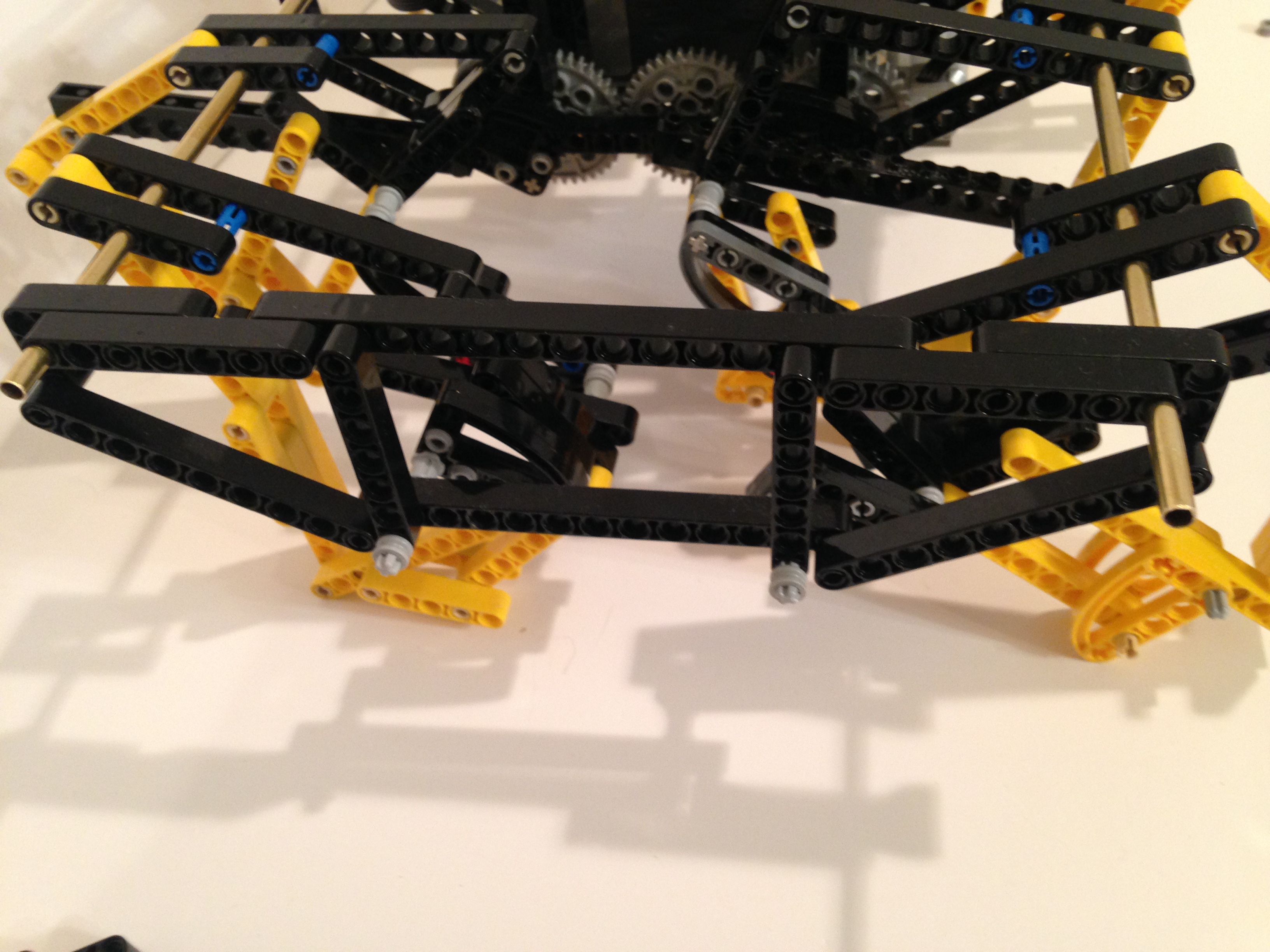
Once the metal support rods lock the diagonals into triangles this frame is as strong as it looks!
Note: you may have noticed that the 9 hole beams I chose to use for the frame's diagonals aren't exactly the correct length, but are close enough, and are described here.
Note: you may have noticed that the 9 hole beams I chose to use for the frame's diagonals aren't exactly the correct length, but are close enough, and are described here.
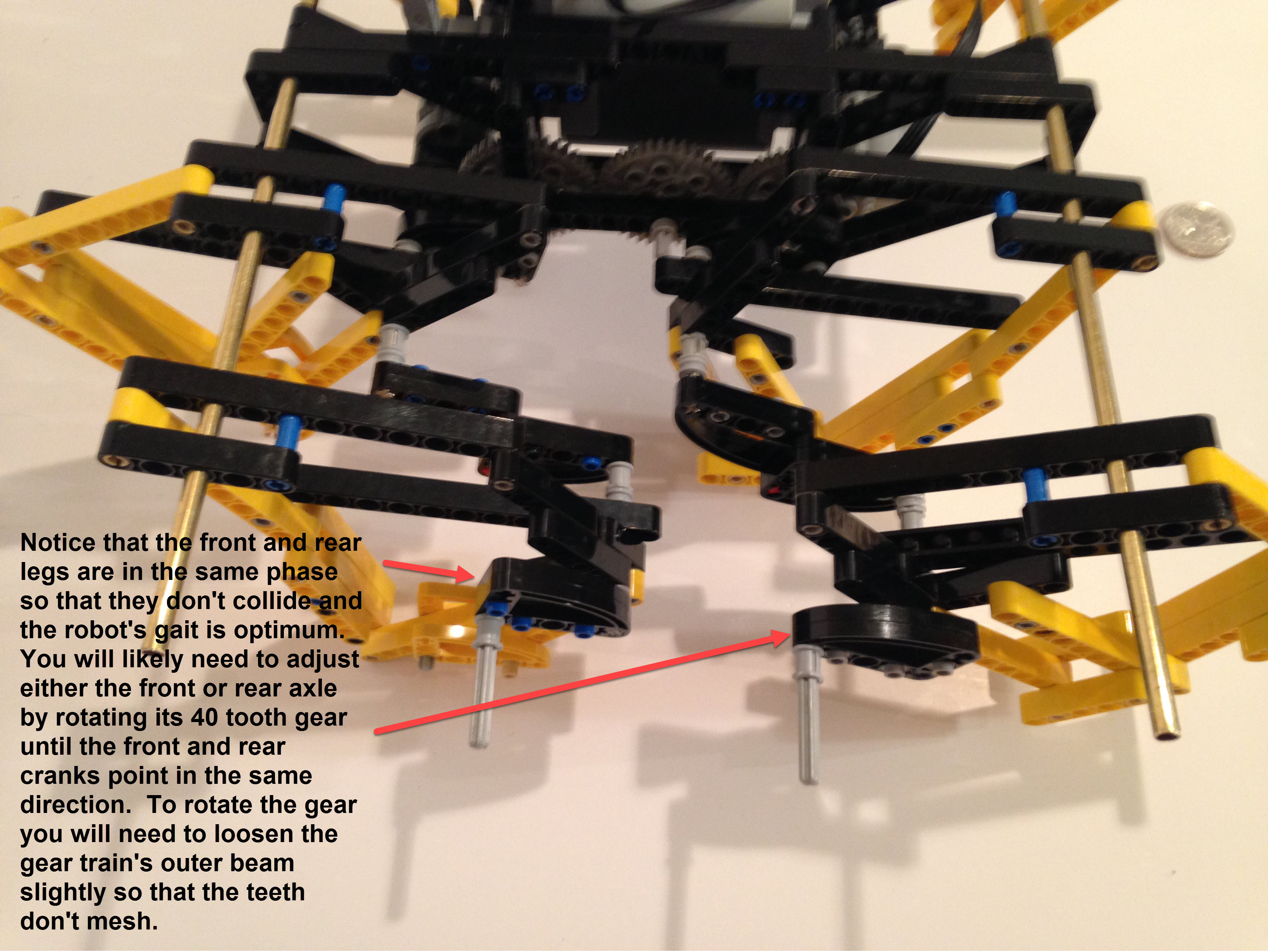
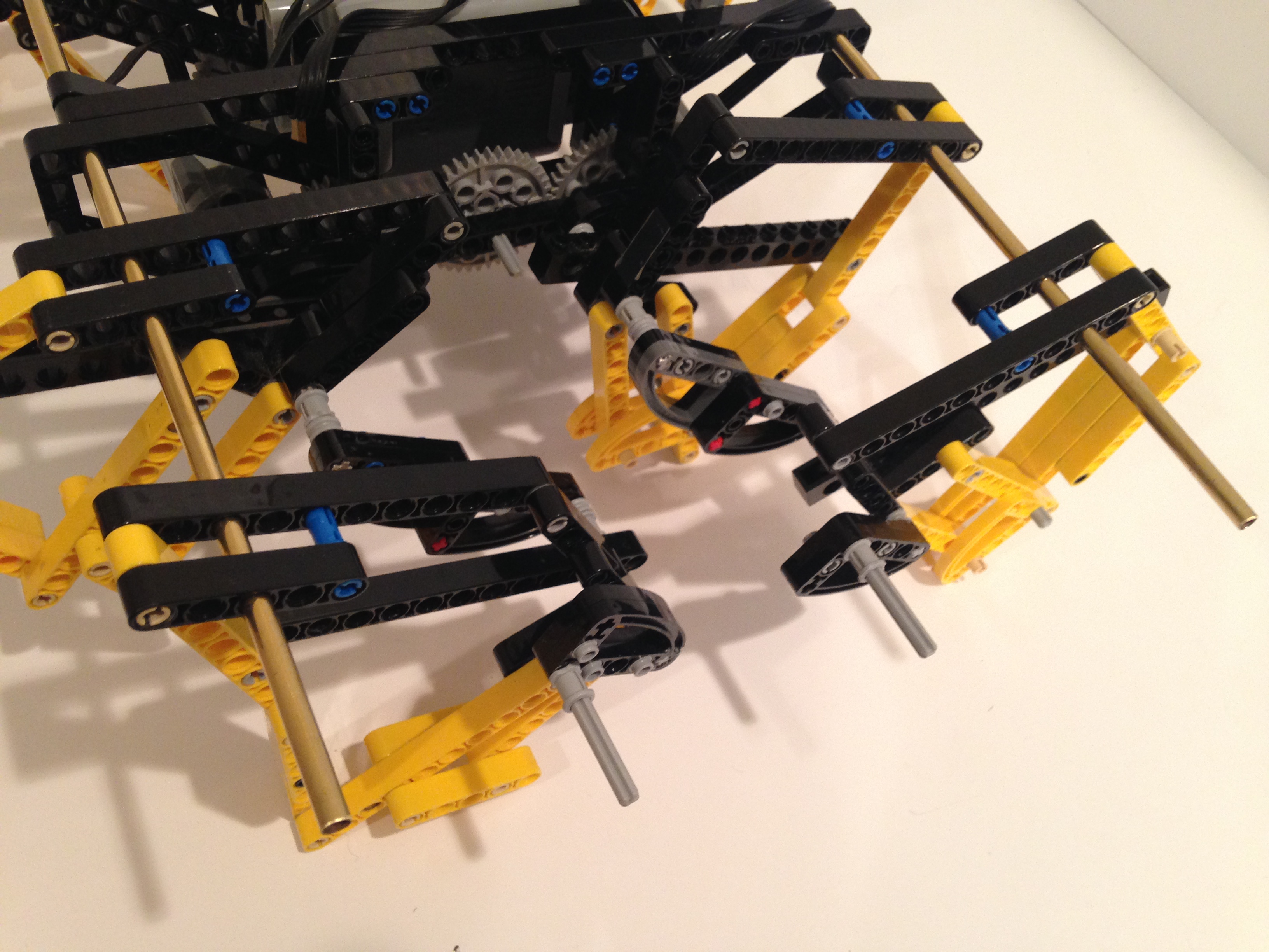
When I say the front and rear legs should be in the same "phase", I mean that the leg's cranks should both pointing in the same direction. In terms of a clock, if one crank is pointing at 9 o'clock then a crank 180 degrees out of phase is pointing at 3 o'clock.
To illustrate the point in action, the following sim shows the front and back legs moving in the same phase (since they share the same crank in the sim), as well as the adjacent pairs of legs moving 180 degrees out of phase.
To illustrate the point in action, the following sim shows the front and back legs moving in the same phase (since they share the same crank in the sim), as well as the adjacent pairs of legs moving 180 degrees out of phase.
For TrotBot's 2 support rods I used 3/16 inch OD Brass tube, but solid aluminum rods work fine as well and may have less risk of bending. Both rods were cut to 16 inches in length, and be sure to file the cut smooth so that the legs parts can slide on easily.
Slide the legs on, being sure to pass the rod thru the 3rd hole from the end of each leg's "shoulder".
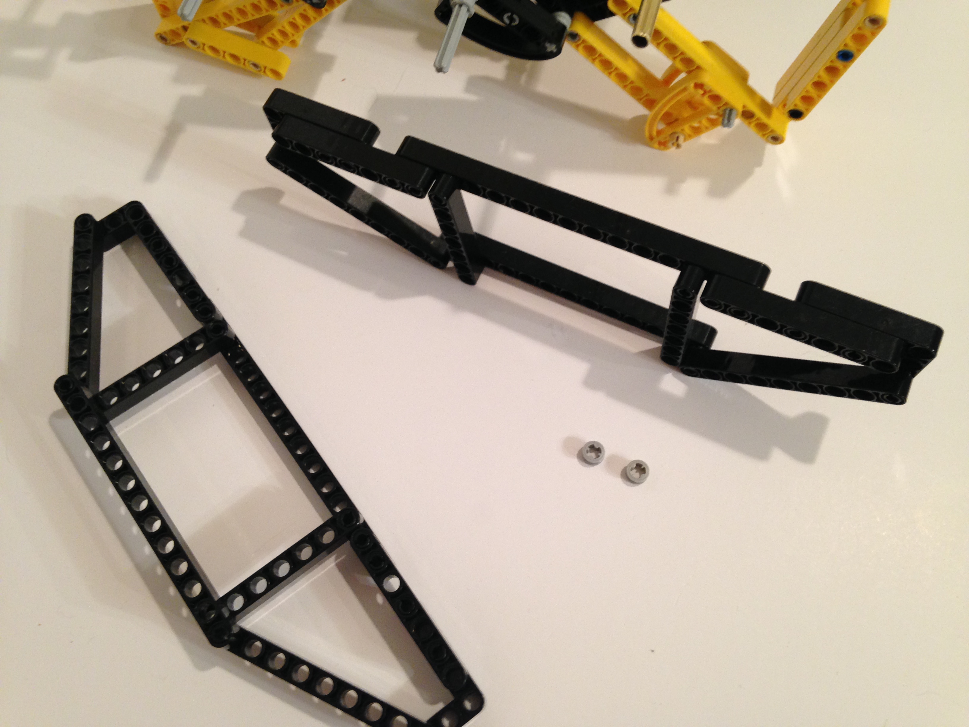
Next, build and add the outer frames, which are very similar to the sides of the inner frame except for the lack of the battery box connections.
Slide the legs on, being sure to pass the rod thru the 3rd hole from the end of each leg's "shoulder".
Next, build and add the outer frames, which are very similar to the sides of the inner frame except for the lack of the battery box connections.
These outer frame triangles help to match the axle's center of rotation to the inner frame's, and also keep the support rods at the correct distance from the axle so that the linkage moves as designed.
Finished!
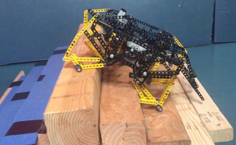
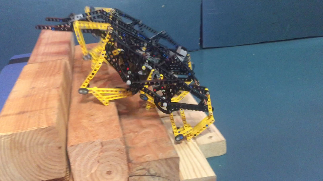
Add wheelie bars and rubber tires to the feet to improve TrotBot's climbing performance

