4-Bar Walking Linkage Optimizer
Posted by Wade
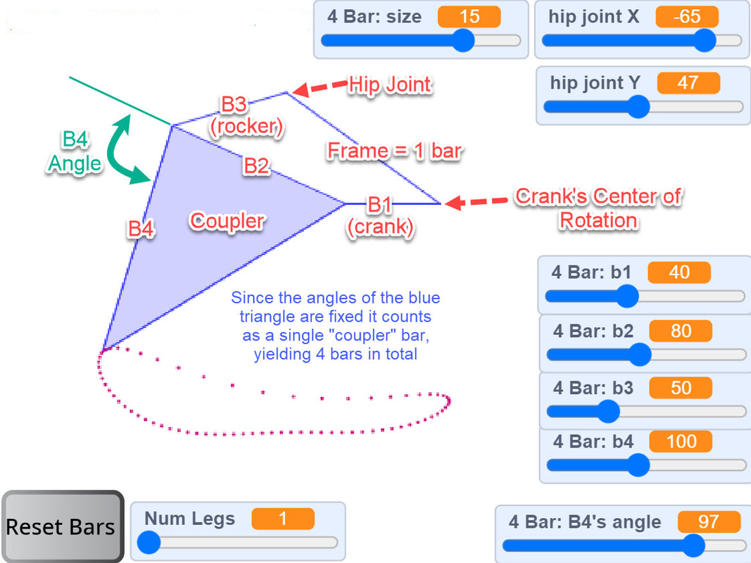
This interactive simulator allows you to quickly check how changing the linkage's bar lengths affect the foot-path it draws as the crank is rotated.
This interactive simulator allows you to quickly check how changing the linkage's bar lengths affect the foot-path it draws as the crank is rotated.
|
Spot Micro Ver 2 with longer legs that will collide with the rear legs unless the front and rear cranks are separated
|
Here is the a video of the simulator in action, and the actual simulator can be found at the bottom of this page
The linkage simulated in the video above can be built in LEGO using the parts below which are 1/10th the scale of the simulation's bar lengths:
Jeep2003's awesome mechanical ostrich uses a similar 4-bar linkage:
As does James Bruton's Robot Centipede:
And check out MaxBrix's tiny 4-bar linkage walker!
|
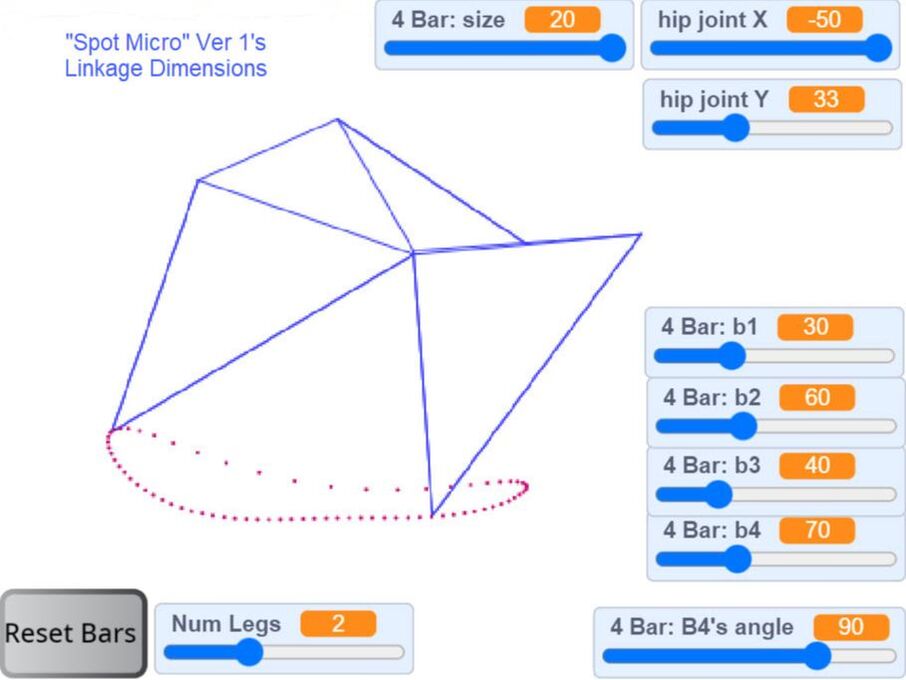
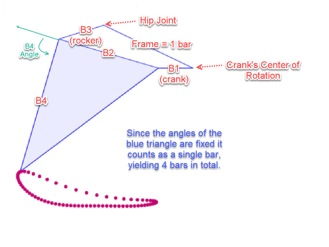
The below "Spot Micro" uses the linkage dimensions shown in the image to the right, scaled up by 10x to make it easier to fine tune the linkage such that the crank length (bar b1) equals 30 in the simulator and is 3 LEGO holes in the build below. A building tutorial is on our LEGO Spot Micro page. |
|
Version 2 below is a bit bigger and steps a little bit higher:
Below are the linkage dimensions we used for Spot Micro Ver 2, scaled up by 10x the LEGO version to allow the linkage to be more finely tuned. Its dimensions are the same as the GIF at the top of this page except for shorter legs so that the front/rear feet don't collide when the crank is in the 12 o'clock position - the GIF's bar B4 was 100, whereas the LEGO version used 90. (NOTE: the image below was created with our 6-bar linkage optimizer where I set bar B5 to 0, and bar B7 to 20. Instead, I could have used this page's 4-bar linkage simulator and set B4's angle to 99 degrees for the same result.)
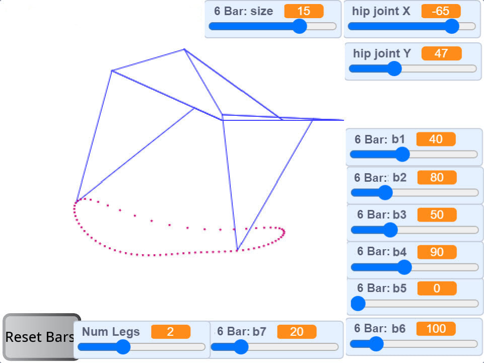
Linkage dimensions of Spot Micro Ver 2, using our 6-bar optimizer which doesn't use an input angle for B4 and instead uses bars B6 and B7 to make a lower triangle which results in an angle for B4 of 99 degrees
|
Below is the interactive simulator. It allows you to simulate between 1 and 4 legs to make it easier to gauge the amount of foot contact at each corner of the robot. The sim is started by clicking the green flag. You can also run it on MIT's site where you can modify the Scratch code. After changing a bar's length, click somewhere other than a slider bar and then press the space bar to see the new linkage, and use your keyboard's left/right arrows to rotate the crank. Standard caveat: just because something looks good in a simulation does not necessarily mean it work well when built, at least not without some tinkering such as mitigating the tendency of knee joint's to hyperextend inward (dead point). |

|
A description of the algorithms, and how we used them to simulate linkages, is here.
When building a simulated linkage in LEGO, remember to use beams with one more hole than the bar's length. For example, a bar of length 8 requires a LEGO beam with 9 holes, because when determining the length of LEGO beams, the first hole is always counted as zero.