The ABC's of Walkers, Big and Small
Posted by Wade
Before going into some of the details of building mechanical walkers, lets first take a look at what makes them tick: their linkages.
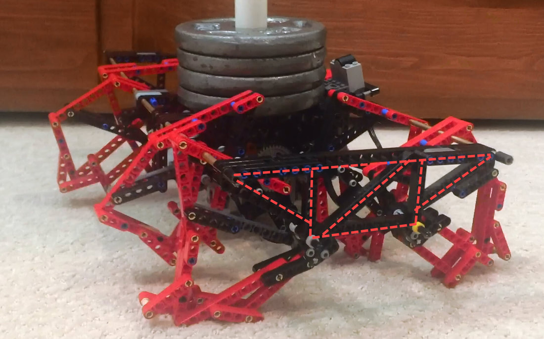
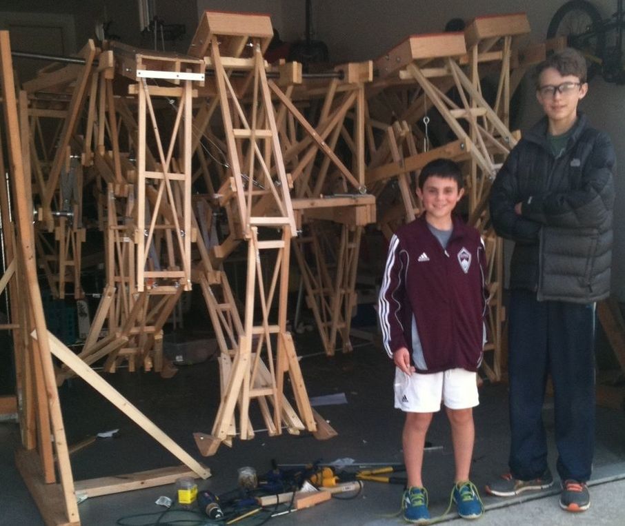
The two dimensional nature of these linkages makes them easy to play with via LEGO Technic beams, which is how we discovered TrotBot's and Strider's linkages and tested their initial performance. Then, after running some optimization code and applying some structural engineering, Team TrotBot was able to turn our LEGO TrotBot into this:
Did you notice our safety (bike) helmets?
Walkers and Linkages
Everything that walks uses muscles or motors to move legs in the manner required. Mechanical walkers are no exception, but rather than moving legs with numerous muscles or motors, mechanical walkers utilize linkages to transform the rotational motion of an engine to the linear motion of a foot sweeping across the ground. Some linkages can do this in an amazingly lifelike manner, such as Theo Jansen’s Strandbeest, and others can result in robust walking machines, such as Joe Klann’s Mechanical Spider mechanism, which is robust enough to have been implemented in the 14,000 pound Walking Beast, designed and built by Martin Montesano:
Mechanical Linkages
Mechanical linkages are all around us, from simple linked-levers like scissors, to more complex systems like windshield wipers or mountain bike suspensions. Even our knees utilize 4-bar linkages. In essence, linkages “link” bars to one another at rigid joints that allow the bars to move, like how the links in a bicycle chain can rotate around their connecting pins. If one of these chain links is fixed to a stationary position, then we can turn a simple chain into a linkage system, and by changing the length of the links and how they are connected to each other in just the right way, the linkage can transform motion at one joint to very different motion at another joint.
For example, the most commonly used linkage is the 4-bar linkage, which tends to be sturdier and more efficient than linkages with higher bar counts. Like all linkages, it can be configured in an infinite number of ways by changing the bar lengths, which can change the linkage's behavior dramatically. Here are a few examples generated with this 4-bar walking linkage simulator:
And here are some of the major categories of 4-bar linkage behavior, created by re-arranging the yellow, white, orange and red bars:
Linkages played a pivotal role in the industrial revolution since they allowed mechanical motion to be transformed to perform useful work, such as transforming the linear motion of a steam engine’s piston to the circular motion required to run a factory’s machines, and without the need of electronics or computer control. While linkages are still very important, more complex motion can now be generated with the help of computer control of additional motors.
Single Degree of Freedom Linkage Mechanisms
A linkage mechanism with a single degree of freedom (DOF) means if a single joint or bar is moved, then all of the remaining bars have to move in response. Hence, they only require one motor to control one bar, whereas mechanisms with 2 DOFs require 2 motors controlling 2 bars, 3 DOFs require 3 motors controlling 3 bars, etc. With single DOF mechanical walkers, the bar that is moved is typically a crank that is connected to a crankshaft and motor . Single DOF mechanisms can make designing walking robots both easier, and harder. Single DOF mechanism design can be easier since the control and timing of only one motor has to be considered. On the other hand, mechanism design can be harder since walkers may require specific leg motion that is impossible to generate with a single DOF mechanism, or the motion may require an overly complicated linkage system, a "kluge".
Straight-Line Linkages
Straight-line linkages are especially useful since they transform circular motion at one joint to linear motion at another joint, or vice versa, and allowed the steam engine to replace the water wheel, dramatically accelerating the industrial revolution. Mechanical walkers typically use linkages that approximate straight-line motion, and some of the most famous straight-line linkages are simulated here.
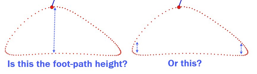
The "Ideal" Foot-Path
We call the path drawn by the foot as the axle is rotated the "foot-path", or "locus":
Linkages played a pivotal role in the industrial revolution since they allowed mechanical motion to be transformed to perform useful work, such as transforming the linear motion of a steam engine’s piston to the circular motion required to run a factory’s machines, and without the need of electronics or computer control. While linkages are still very important, more complex motion can now be generated with the help of computer control of additional motors.
Single Degree of Freedom Linkage Mechanisms
A linkage mechanism with a single degree of freedom (DOF) means if a single joint or bar is moved, then all of the remaining bars have to move in response. Hence, they only require one motor to control one bar, whereas mechanisms with 2 DOFs require 2 motors controlling 2 bars, 3 DOFs require 3 motors controlling 3 bars, etc. With single DOF mechanical walkers, the bar that is moved is typically a crank that is connected to a crankshaft and motor . Single DOF mechanisms can make designing walking robots both easier, and harder. Single DOF mechanism design can be easier since the control and timing of only one motor has to be considered. On the other hand, mechanism design can be harder since walkers may require specific leg motion that is impossible to generate with a single DOF mechanism, or the motion may require an overly complicated linkage system, a "kluge".
Straight-Line Linkages
Straight-line linkages are especially useful since they transform circular motion at one joint to linear motion at another joint, or vice versa, and allowed the steam engine to replace the water wheel, dramatically accelerating the industrial revolution. Mechanical walkers typically use linkages that approximate straight-line motion, and some of the most famous straight-line linkages are simulated here.
The "Ideal" Foot-Path
We call the path drawn by the foot as the axle is rotated the "foot-path", or "locus":
|
And here are the phases of the foot-path as defined by mechanical walker pioneer Professor Joseph Shigley: |
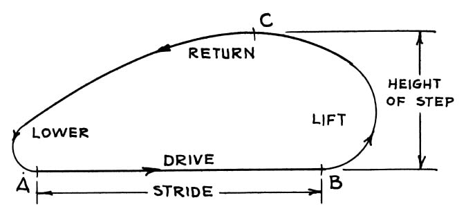
Shigley's Phases of the Foot-Path
|
What constitutes an "ideal" foot-path depends on the scale of your build. For heavy, SUV-scale walkers the priority should be a smooth and steady gait that approaches that of a wheeled vehicle, otherwise the heavy weight will result in poor performance. In other words, when the feet are in contact with the ground:
- their path should be as flat as possible so that the machine doesn't bounce, which would also increase the torque and power required to walk, as you can see in this experiment with TrotBot.
- their horizontal speed should be as uniform as possible so that they don’t skid or shake the machine, and don't consume power from constantly accelerating/de-accelerating the robot. If the foot-speed varies, then the addition of a hinged foot with a curved bottom can help because it will passively rotate in compensation, as you can see in this experiment with Klann's mechanism.
The Speed of Klann Linkage Robots can be Smoothed with Feet that Slide or Rotate
Below highlights the foot-contact with the ground, and the horizontal foot-speed of Strider, Strandbeest, TrotBot, and Klann linkages.
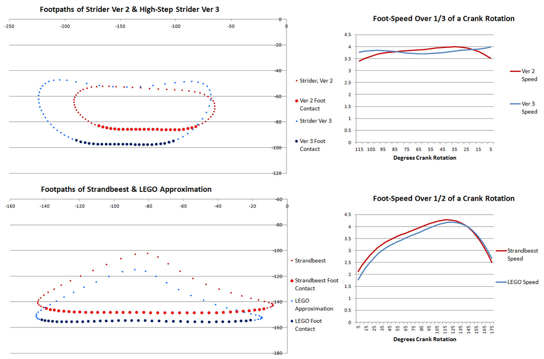
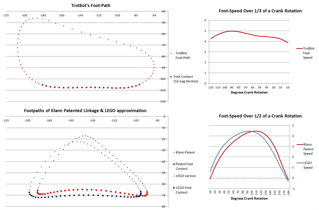
Footpaths and Speed of Strider, Strandbeest, TrotBot and Klann Linkages (without adding feet)
Note: the horizontal foot-speed is calculated by taking the difference between the X values of adjacent points of the foot-path when the feet are in contact with the ground. Therefore, when the plotted points are close together the speed is slow, and when they are far apart the speed is fast.
To approach the efficiency of a wheel, the speed of the feet when in contact with the ground should be constant. Strider Ver 3 (the top graph above) has relatively constant speed, resulting in an efficient gait - it's the only mechanism that we've tested which can walk with a 1:1 gear ratio without the LEGO motors stalling:
To approach the efficiency of a wheel, the speed of the feet when in contact with the ground should be constant. Strider Ver 3 (the top graph above) has relatively constant speed, resulting in an efficient gait - it's the only mechanism that we've tested which can walk with a 1:1 gear ratio without the LEGO motors stalling:
Rugged Terrain
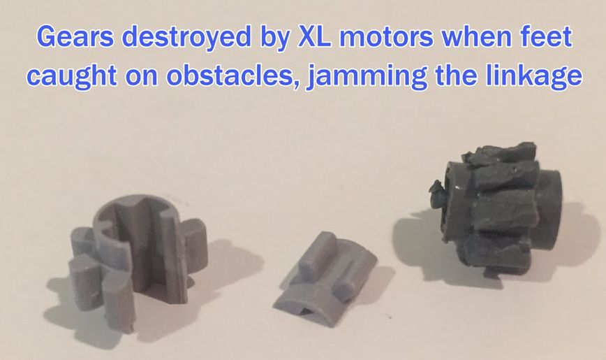
For smaller-scale walkers where weight isn't as much of an issue, the priority can shift toward navigating rugged terrain, as kids invariably like to do when they make piles of debris to drive our LEGO walkers over. In this case, a high foot-path is desirable, otherwise feet can catch on obstacles, which can jam the linkage and cause gears to grind. To avoid jamming, walking linkages should have a high, oval-shaped foot-path, always ready to lift their feet over obstacles. In contrast, triangular foot-paths may be high at the center, but feet can still catch on obstacles at either end:
Walking Robots with Triangular Foot-Paths Tend to Jam on Obstacles
|
If feet get stuck on obstacles it jams the linkage. If LEGO's XL motors are used, then jamming the linkage can quickly destroy your gears, like this: |
|
Furthermore, oval-shaped foot-paths are better suited for rugged terrain than are teardrop-shaped foot-paths, because the narrow end of the teardrop means the robot won't be able to reverse out of terrain that got too rugged, leaving it stranded, or that it can get stuck astride obstacles.
For example, if we modify Klann's linkage to create a teardrop-shaped foot-path like so:
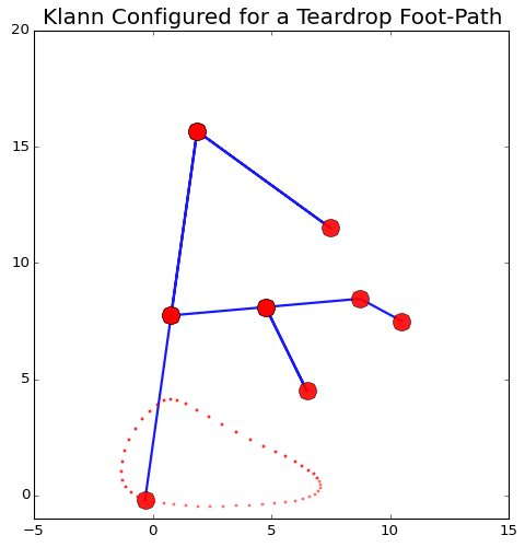
Then here's what can happen when this configuration encounters obstacles:
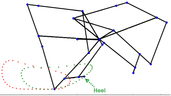
TrotBot's foot-path is also somewhat tear-drop shaped, but by adding a "heel" TrotBot steps about as high in both directions to avoid getting stuck astride obstacles. Without its heel, TrotBot's rear legs probably wouldn't have cleared a few of the 2x4s in the following video.
|
TrotBot with Heel Linkage
|
Klann's ability to clear obstacles is also improved by adding a claw-like "heel" to the inner side of it's legs:
A Better Gauge of Performance on Rugged Terrain is the Ground-Perspective Foot-Path
Foot-paths are usually analyzed from the perspective of the moving robot like in the simulations above, but obstacles on the ground are not moving. Therefore, to determine how well a robot can step over obstacles we should also consider the ground-perspective foot-path by plotting it as the robot is moving. As you can see in the following simulation, the robot's horizontal speed flattens both the lift and lower portions of the foot-path, increasing the likelihood that feet will jam on obstacles.
Below is Strider's Ver 3 linkage, which we optimized for a consistently high ground-perspective foot-path to minimize foot jamming:
Strider Linkage Optimized for a Consistently High Ground-Perspective Foot-Path
Another noteworthy feature of Strider's foot-path is how the bottom halves of the lift and lower phases are nearly vertical, which means the robot will have less of a tendency to slow down when stepping on/off obstacles or when the terrain's slope changes abruptly, resulting in a more efficient gait on non-flat terrain.
In contrast, walkers with triangular foot-paths require fewer legs, but they are more likely to slow down or jam at slope changes, as can be seen in the following experiment comparing Klann's and Strider's linkages. While legs often beat wheels on rugged terrain, when it comes to simple slope changes like when driving a walker up a slope of an elevated garage, wheels beat mechanical legs if the legs have triangular foot-paths.
How robot speed varies as ground height changes can also be gauged by simulating the front legs while keeping the mechanism horizontal, as it will be when it initially encounters ground height changes:
Minimizing the Number of Legs Required by Walkers
To minimize the number of legs a walker requires, the linkage should maximize the percentage of time the foot is in contact with the ground per crank rotation. To say it another way, the linkage should minimize the percentage of time it takes the foot to be lifted and returned to the front of the foot-path. However, accelerating the lifted foot can cause vibration problems since it exerts intermittent forces on the robot via Newton's 2nd and 3rd Laws of Motion. Vibration is especially problematic at larger scales since the forces involved are proportional to the scale raised to the 4th power (mass tends to be proportional to scale cubed, and acceleration is proportional to scale, then apply F=MA).
This leg mechanism's accelerations at the top corners of its foot-path could cause high-speed vibration problems, especially at scale
Linkage Optimization and Trade-Offs
If you play with linkage configurations you will likely find that emphasizing one feature, such as a high, oval-shaped foot-path, can cause a degradation in other features, such as reduced foot-contact with the ground due to having to trace a 4-sided foot-path with a longer perimeter. To help with balancing these trade-offs, keep in mind the scale of your build. Also, modifying a linkage may create a "dead point", or "change point" that you'll need to manage - below is an example of blocking the change point of a parallelogram linkage, and here are some other ideas for managing dead points in a variety of walkers.
Here are a few simulators for visually optimizing leg mechanisms, or for making LEGO approximations of mechanisms. For example, below is Jansen's leg mechanism alongside a LEGO approximation of it, which was easy to find with some help from this Jansen linkage calculator.
Here are a few simulators for visually optimizing leg mechanisms, or for making LEGO approximations of mechanisms. For example, below is Jansen's leg mechanism alongside a LEGO approximation of it, which was easy to find with some help from this Jansen linkage calculator.
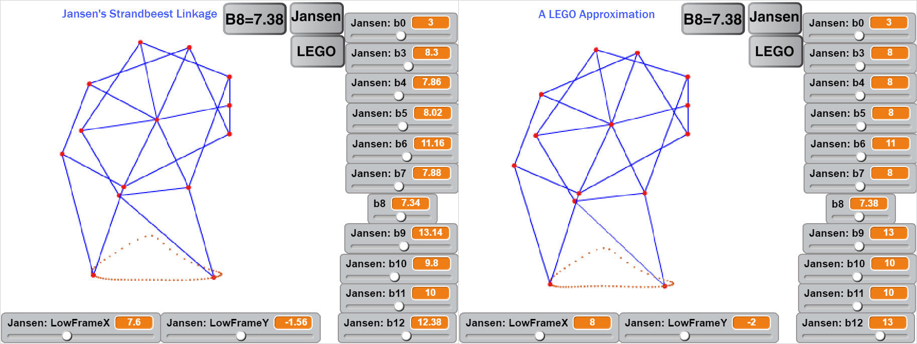
Theo Jansen's Strandbeest Linkage, Scaled so that the Crank=3, and a LEGO Approximation
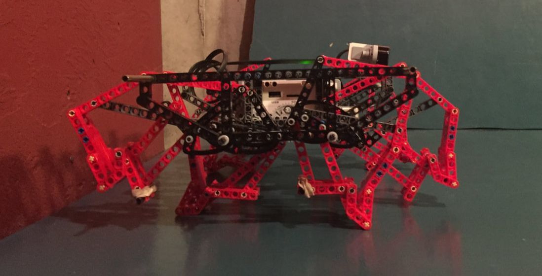
Here's the above LEGO approximation of Strandbeest implemented with 8 legs:
And here's a Klann linkage calculator for customizing Klann's leg mechanism:
Walker Stability
The requirements for walker stability varies greatly depending on their size. Small-scale, 8-legged walkers can often get away with only three feet on the ground, which may cause them to shuffle or lumber as they move about, but may not impair their ability to walk. In many cases this can look very interesting, and sometimes the more a walker lumbers, the more lifelike it seems. However, the larger the walker is, the more the lumbering will take its toll on walking performance, efficiency, and ultimately, the parts. Thus, having four feet in contact with the ground at all times like a four-wheeled vehicle is usually a requirement for large-scale mechanical walkers. With our first version of our SUV-scale TrotBot we only had three feet on the ground during portions of the axle's rotation. This also occurred at LEGO-scale where it wasn't a problem, but when our SUV-scale version encountered these tripod points the entire machine would bend and the fourth foot would crash into the ground, where it would then skid since it's horizontal speed was too slow at that point in its foot-path. After this discovery we had to add a lot of modifications to get a decent walk out of TrotBot Ver 0, such as the addition of active feet, which increased each leg's percentage of ground-contact per crank rotation .
TrotBot with Active Toes
We also found that fixed-angle toes can smooth some walker's gaits, like those used by Strider's linkage:
Strider Linkage with and without Toes
......as can shock-absorbing heels (more details here):
Hexapod Stability
Six-legged walkers are stable with only three feet on the ground if their feet are arranged like an equilateral triangle, which is how we designed Hexapod TrotBot. However, just like how 3-wheeled, tripod cars are less stable than standard, 4-wheeled cars, mechanical walkers with 3 feet on the ground are less stable than those with 4 feet on the ground, and hexapod walkers with tripod gaits don't perform as well on rugged terrain as their 8-legged versions.
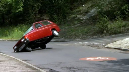
3-Wheeled, Tripod Car
|

Hexapod TrotBot with a Tripod Gait
|
TrotBot with Legs Timed for a Tripod Gait

Credit: The Smithsonian Channel (click the image to see their video)
Side comment: running carnivores tend to land front leg first, and large herbivores tend to land rear leg first - why? Perhaps it is inefficient for herbivores to flex their backbones like cats and dogs due to their large guts?
|
When horses buck they also flex their backbones....and land on their front feet
|
A Dynamic Structural Engineering Challenge
Walkers are subjected to more stress than are wheeled vehicles. In order for walkers to bear the stress with a minimal amount of structure and weight, it is a good idea to think of them as a statics problem, similar to the structural engineering challenges of building a strong bridge - with the additional challenge that the bridge’s support columns will be moving under the it!

Dinosaur Bridge?
|
If you are building walkers at LEGO-scale, this shouldn’t be a significant problem, and here are some ideas for how to make strong, triangle-based frames with LEGO's Technic beams. However, as objects are scaled up the strength of the object increases at a rate lower than that of the weight, because strength tends to be proportional to the square of the scale (the surface area), whereas weight tends to be proportional to the cube of the scale (the volume). This reduction in strength-to-weight ratios as scale increases explains why ants can lift 100x their weight, and also why if an ant were enlarged to human size they probably couldn't even stand, let alone lift a car. Scaling up a walker means you have to solve this strength-to-weight ratio problem, and the larger the walker is, the more challenging this problem will be. |
Strider's Trussed Frame
|
'>
TrotBot's frame triangles easily handled this 10 pound load test (click image to see the test)
Walkers with bumpy gaits subject frames and legs to even more stress, and the resulting problems will increase as scale increases. Larger scales require more structure and motor power to handle the heavier weight, which further increases weight and requires even more structure, power, and costs. To help prevent weight and cost increases from spiraling out of control, remember that the larger your walker, the smoother its gait should be. Also, the leverage of long legs can put a tremendous amount of force on the leg's joints when walking on uneven terrain or when turning them tank-style, so trussing the legs to increase strength with minimal weight should be considered, especially in the sideways dimension.
|
Sideways Forces on Legs When building large walkers it is important to remember that the legs possess a side-to-side, or "Z" dimension as well. While this seems obvious, the 2D nature of many walking linkages can lead designers to primarily think of them in the 2 dimensional plane where their linkage behavior occurs, which is why they are also called "planar mechanisms". While the Z dimension has no impact on the linkage characteristics of planar mechanisms, building the leg sections wide is important from a structural engineering perspective, otherwise sideways or "lateral" forces, and the resulting torque on the joints can snap the legs like twigs, especially when turning walkers tank-style. The way that we solved this problem with TrotBot was to truss each leg in the sideways dimension, creating lightweight but effectively very wide parts that could withstand lateral forces. |
|
To illustrate the strength gained by trussing, TrotBot's leg in the above video weighs only 6 pounds, but 4 of them were able to support TrotBot's 450 pounds six feet above the ground, while lumbering no less.
Support Rods
If a walker's legs are located far from the inner frame then the design of their connections to the frame becomes another structural engineering challenge. With our LEGO-scale builds we solved this by using metal rods of 3/16" diameter, the approximate diameter of LEGO Technic's beam holes. However, with larger walkers these rods, no matter what material we made them out of, bowed under the weight of the mechanism. Our solution to this problem was lightweight cables linking the bottom of the frame to the support rods, similar to how a Cessna's high wings have diagonal attachments to the fuselage to prevent them from being torn off by the force of lift on the wings. In the below left picture the cables weren't tensioned and you can see the support rods bending in a smile, whereas in the right GIF the cables were tensioned and the support rods are straight.
When the cables weren't tensioned, TrotBot's frame sagged and its support rods bent in a smile
|
TrotBot with its cables tensioned and support rods straight, and with its wide, elephant-like legs and feet, which increase lateral strength.
|
|
An alternative to stiffening the rods via tensioned cables is to add a truss above the rods that can resist compression. |
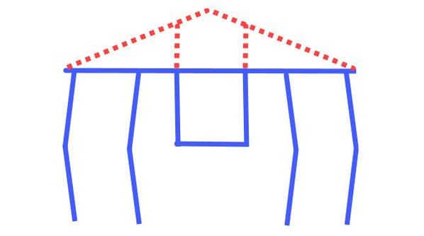
The truss resists compression, preventing sagging under heavy loads
|
|
Walker Width Narrower walkers put less stress on the support rods, and require less structure since the robot's weight is more centered over the legs, similar to how the legs of dinosaurs and mammals can bear weight more efficiently than can the sprawling legs of lizards. Wider walkers are also harder to turn tank-style, since mechanical walkers lack differentials. |
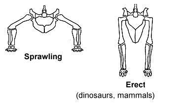
Narrower walkers can bear weight and turn more easily
|
Transmission of Torque (twisting force)
Mechanical walkers typically have 8 to 12 legs configured in front/back pairs, staged out from the frame. This means that torque has to be transferred all the way from the inner frame to the outside leg pair. This can be achieved through a system of cranks attached to crankshafts (axles). However, this system can also become overextended and begin to bow under the robot's weight. Therefore, for large walkers consider supporting this crank/axle system between each leg pair via diagonal beams linking the axle to the support rods.
Torque also needs to be transferred from the cranks to the axles. This is the opposite of bicycle crank arms, where the rider needs the pedal to rotate independently of the rotating crank arms. As walker cranks rotate they need to transfer that rotation to the adjacent crank so they can remain in the correct phase with respect to one another. This is done by locking the joining axle to each crank via keyed axles, or by using square or hexagonal axles and hubs.
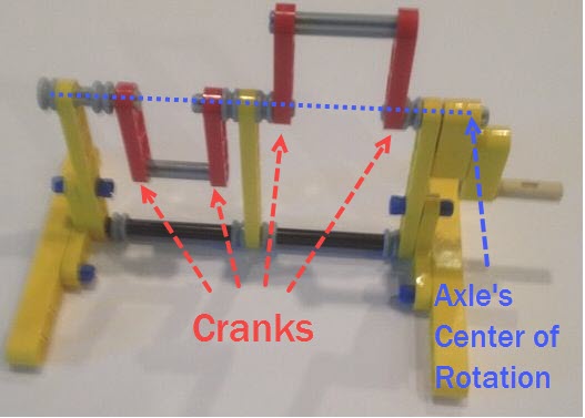
Crank/Axle system in LEGO for driving 2 legs 180 degrees out of phase
If you want some ideas on building crank/axle systems for 12-legged walkers where the cranks need to be 120 degrees out of phase, then check out this blog post.
When building heavy and wide walkers at LEGO-scale, such as walkers using the EV3 brick, you may need to replace LEGO's plastic axles with steel axles, since LEGO's plastic axles twist easily under torque. Large-scale walkers can permanently twist steel axles in the same way if enough torque is applied.
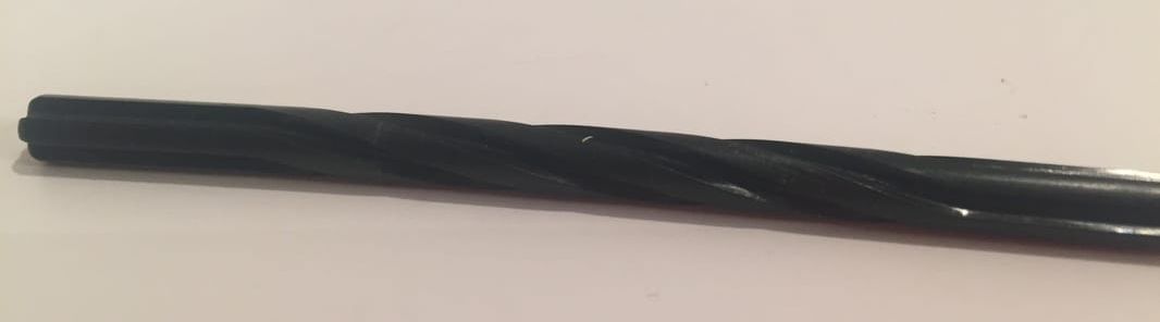
Plastic LEGO axle permanently twisted by a LEGO XL motor (geared down by a 5:1 ratio)
Motorizing Walkers
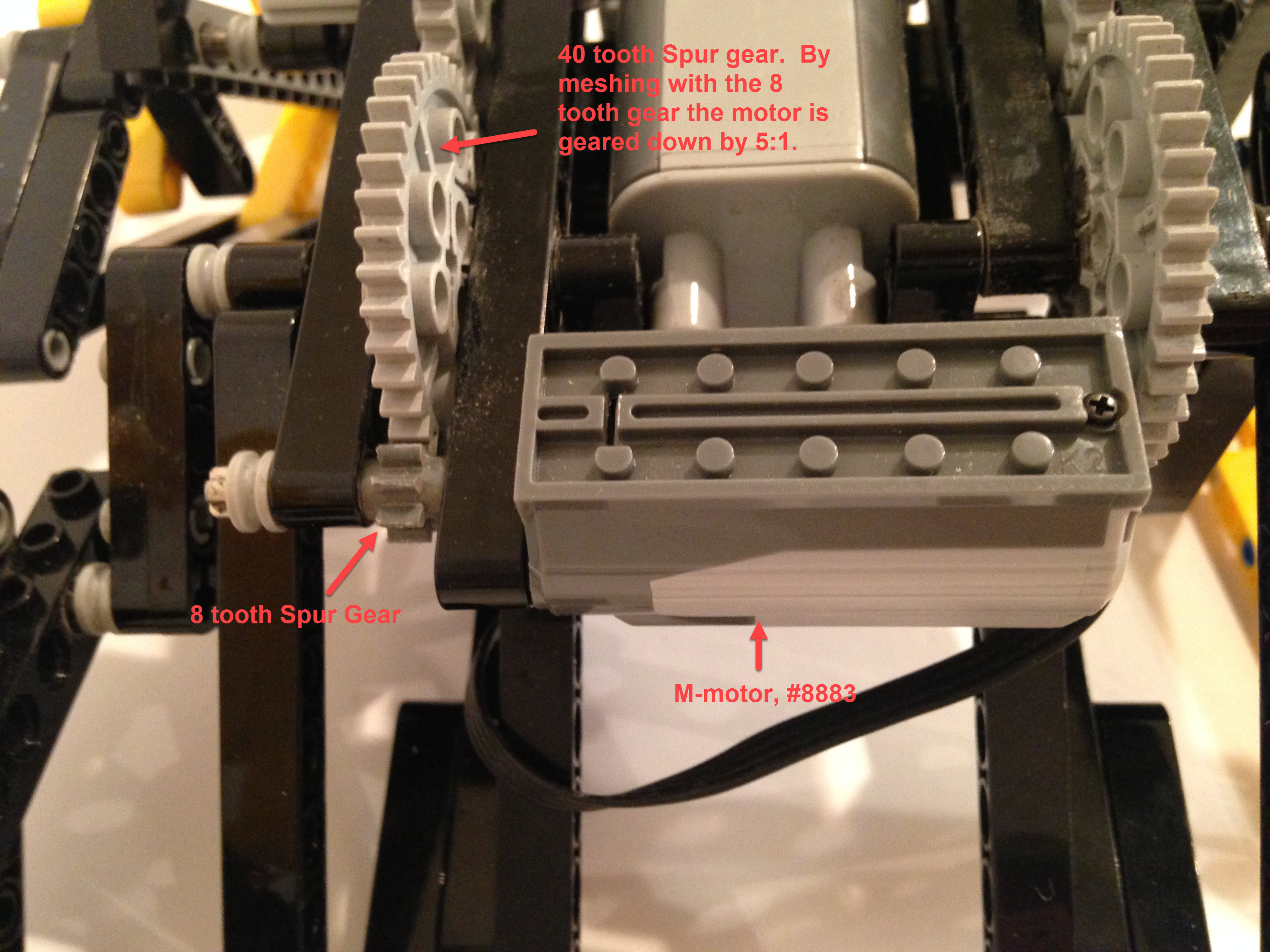
After you solve all these kinematic and structural engineering challenges, motorizing your walker can be the fun part, and is an easy thing to do at smaller scales. However, the motor may need to be geared down because the RPM can be too high for most walkers. Furthermore, one full rotation of the axle for a walker will generally cause its foot to move further than what a wheeled vehicle would - for small wheels at least. Also, without being geared down, the motor's stall torque may be too low for the walker, meaning the robot will be under-powered.
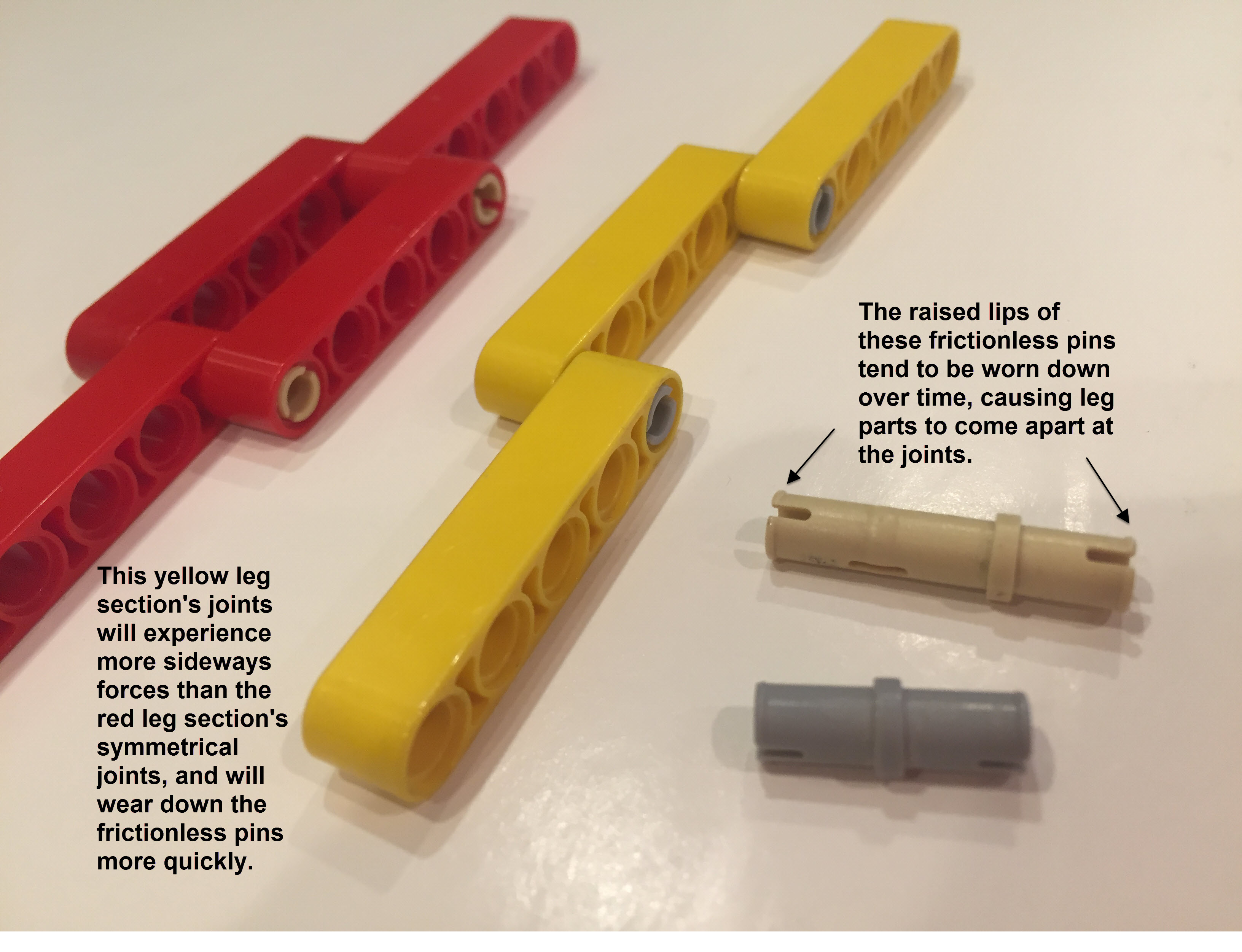
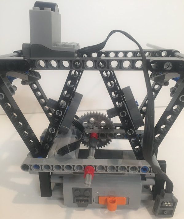
To illustrate, the following image is of the underside of a walker that has been geared down by a 5:1 ratio. It's also worth noting that the 8 tooth spur gear is showing signs of wear, even though it's axle is supported on both sides with Technic beams, and will likely need to be replaced soon.
While on the subject of wear, another LEGO part that walkers tend to wear out after a dozen or so hours of operation are the leg joint's frictionless pins. The raised lips at the end of the pins tend to wear down over time, and the leg parts will no longer join with a sharp "snap", and will tend to come apart. You can reduce this tendency if the leg's joint connections are symmetrical like the red leg section in the image below. In contrast, the yellow leg section's joints will bend sideways somewhat while bearing weight, and will therefore wear the pin's lips more quickly.