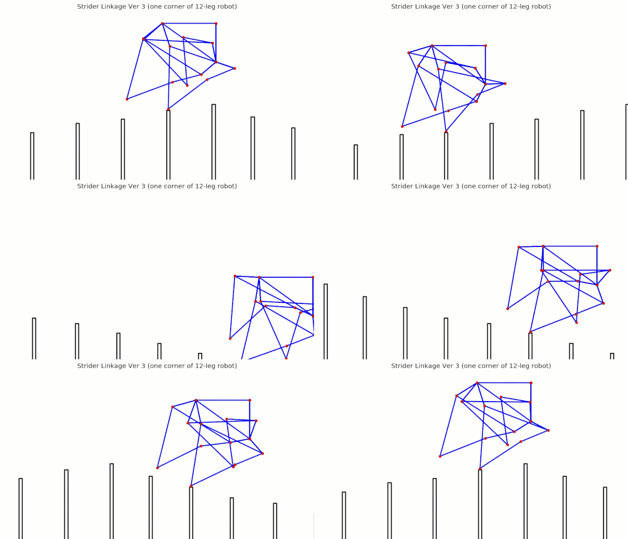
Linkage Simulation
Linkage Algorithms and their Application
Posted by Wade
We wanted to build our simulators DIY-style using math that middle school students could understand, so we initially attempted to derive an algorithm for calculating the joint's X,Y coordinates based on the Pythagorean Theorem (as opposed to a trigonometry-based solution). This derivation turned out to be a bit tricky, so we Googled "circle intersection algorithm" and found Paul Bourke's solution, which employs some clever algebra and the Pythagorean Theorem to solve for the joint's X,Y coordinates, giving us a fast, analytical solution for calculating linkages. His derivation is the 5th one down on this webpage.
We wanted to build our simulators DIY-style using math that middle school students could understand, so we initially attempted to derive an algorithm for calculating the joint's X,Y coordinates based on the Pythagorean Theorem (as opposed to a trigonometry-based solution). This derivation turned out to be a bit tricky, so we Googled "circle intersection algorithm" and found Paul Bourke's solution, which employs some clever algebra and the Pythagorean Theorem to solve for the joint's X,Y coordinates, giving us a fast, analytical solution for calculating linkages. His derivation is the 5th one down on this webpage.
Circle Intersection Algorithm and its Application to Linkages
|
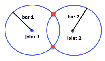
Each bar of a linkage can trace a circle by rotating it around its joint, as shown in the image to the right. Bourke's algorithm calculates the X,Y coordinates of the two red points where the circles intersect. The third joint that links the two bars will be one of these red points, and by considering how the mechanism should function you can determine which of the two points to choose for the joint.
|
Initially, only two joints of a linkage may have known coordinates, such as the crank and a frame connection, which determines which joint can be calculated next. Then, this third joint allows a fourth joint to be calculated, then a fifth, etc.
Because the circle intersection algorithm yields two solutions, our code provides four variables to make it easier to choose between these solutions: High Y, Low Y, Left X, Right X. When calculating a new joint and determining which of these 4 variables to use, consider the path the joint should follow. This should help you to determine which of the 4 variables will always give you the correct intersection point, regardless of the crank's rotation.
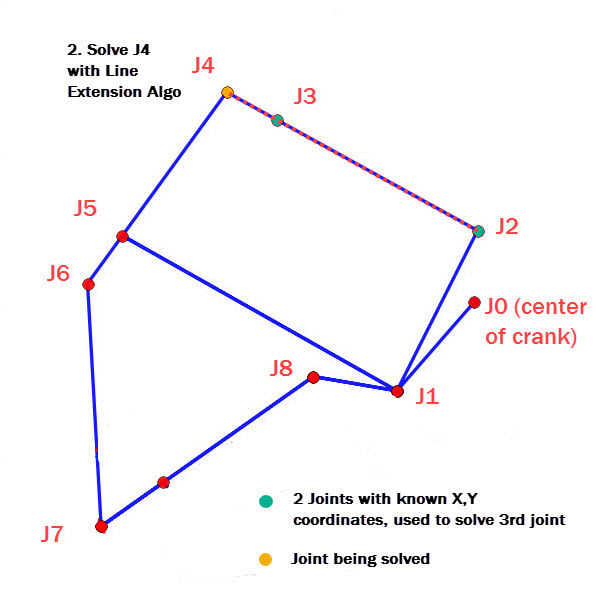
Our code also uses a second algorithm called "line extension", which simply takes the slope of the bar between two joints and extends the bar to the third joint, with an angle if necessary.
Example: Calculating TrotBot's Joints
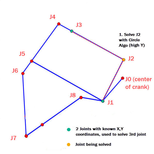
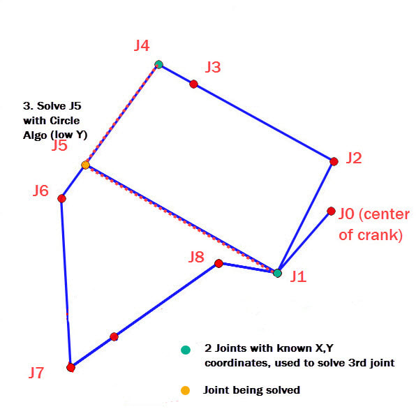
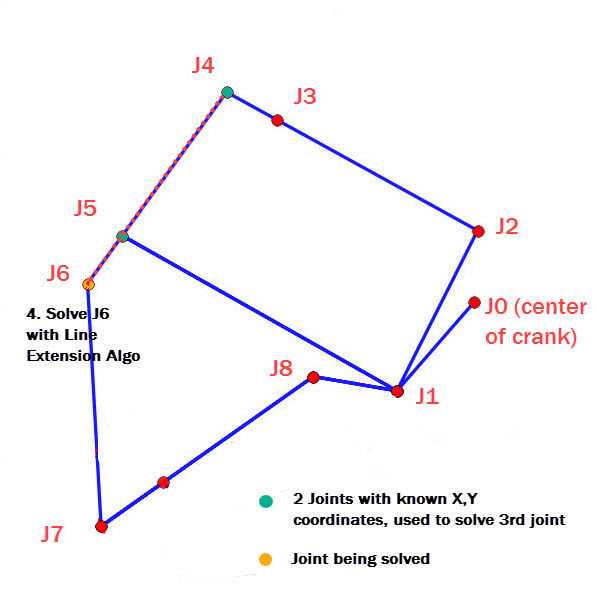
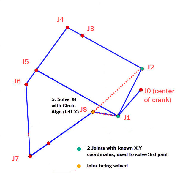
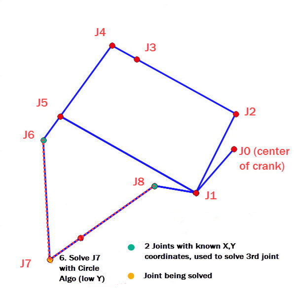
In the following images the joint being calculated is colored orange and the two known joints are colored green. Also, the bars used in the calculations are highlighted with a red dashed line.
1. For a given rotation angle of the crank, all that is initially known are the coordinates of the frame connection J3, and the crank J1. These joints allow joint J2 to be calculated by using the circle intersection algorithm with the solution choice "High Y".
1. For a given rotation angle of the crank, all that is initially known are the coordinates of the frame connection J3, and the crank J1. These joints allow joint J2 to be calculated by using the circle intersection algorithm with the solution choice "High Y".
2. Next, joint J4 can be calculated by extending the line connecting J2 to J3:
2. Next, joint J4 can be calculated by extending the line connecting J2 to J3:
3-6. The remaining four joints can be calculated in the same manner:
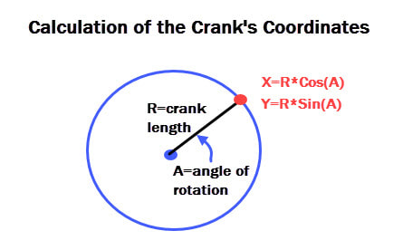
Also, the first joint that needs to be calculated is always the crank, which uses Sine, Cosine and the crank's angle of rotation, as shown below.
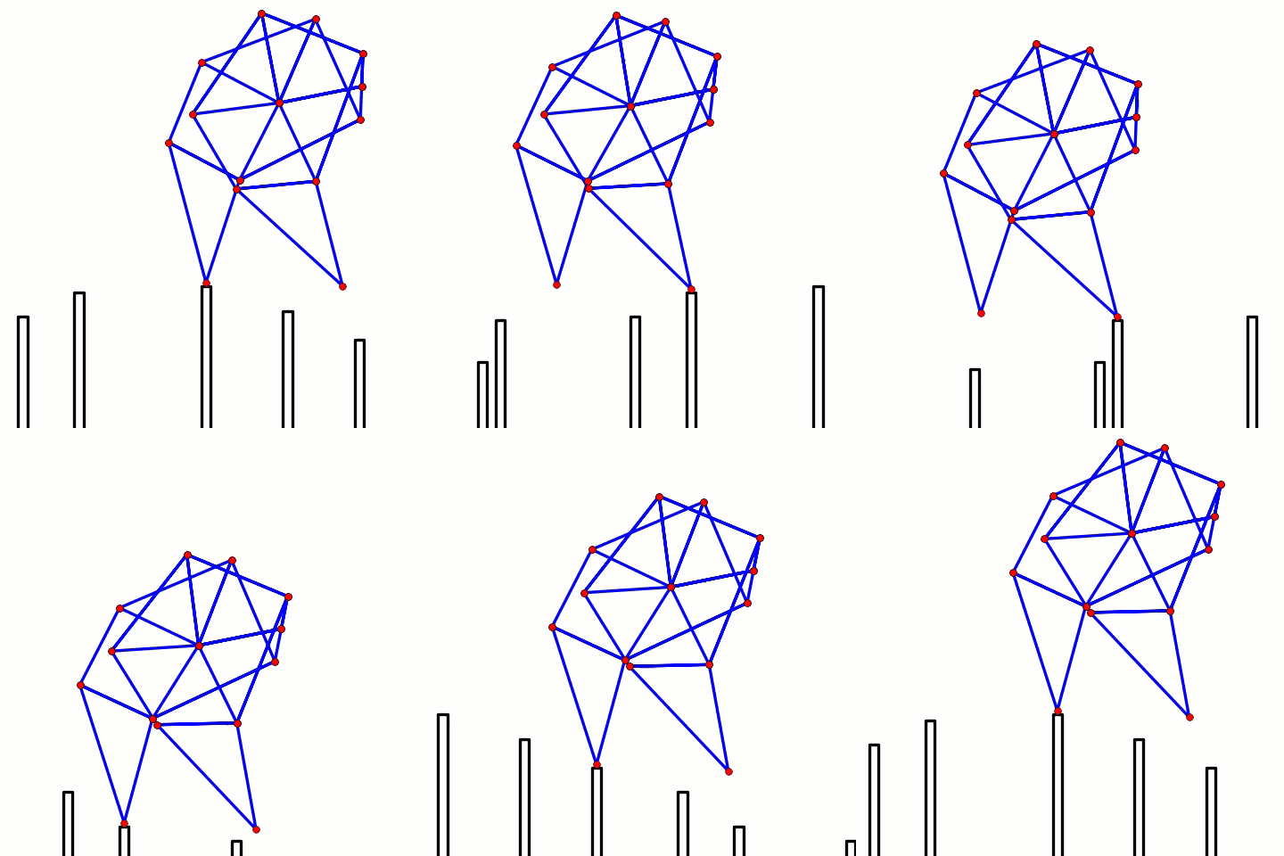
To make the code run faster it should first calculate all the joints' coordinates for one rotation of the crank, and save these coordinates to each joint's dictionary (or list). Then, when the linkage is simulated the crank is rotated, and the joint values are retrieved from the dictionaries, which are used to animate the linkage.
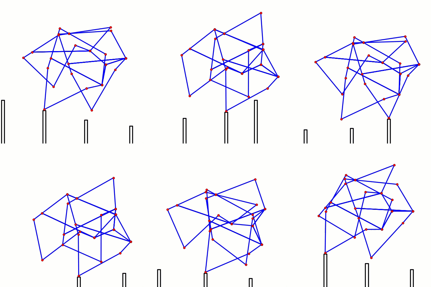
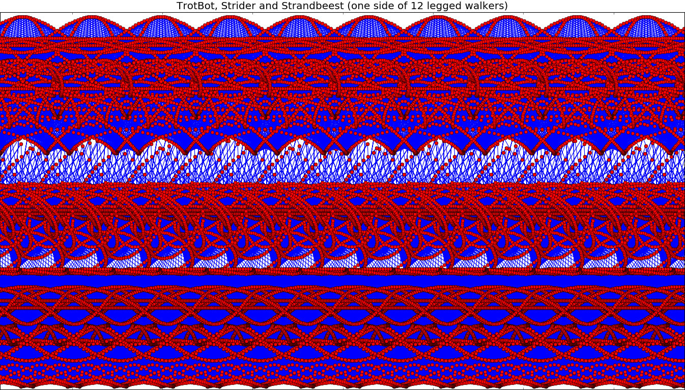
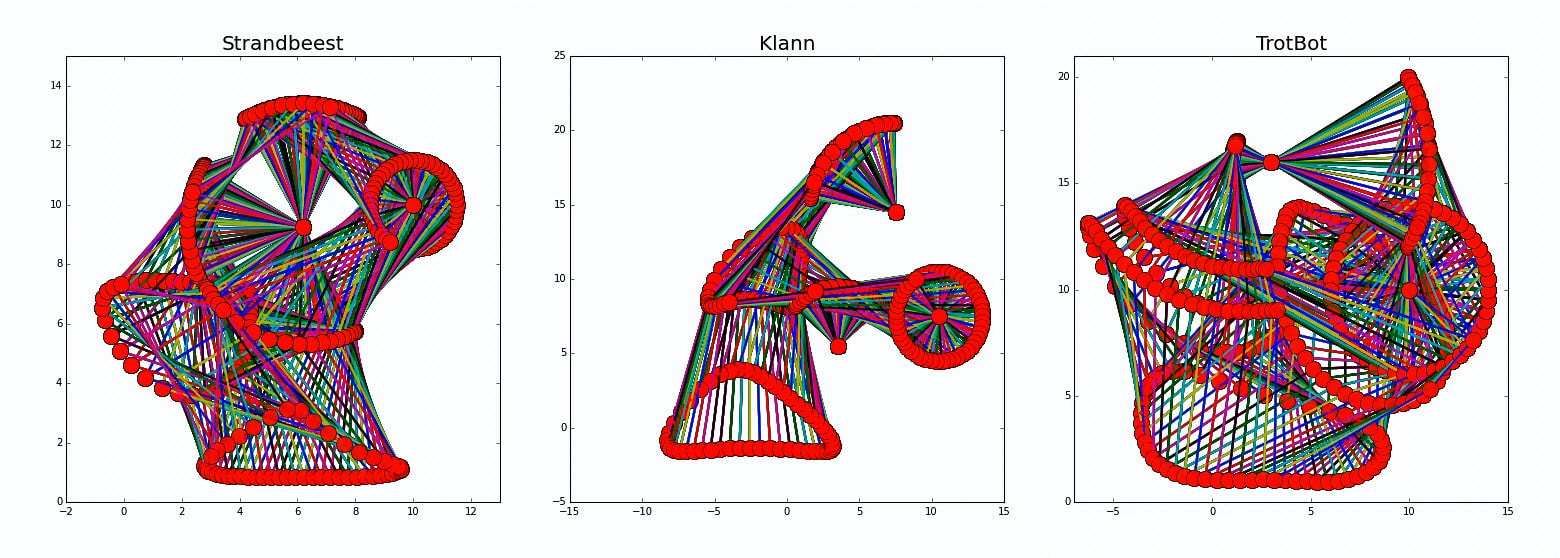
When animating linkages, if you don't delete the previously rendered images, then you get results like the following:
When animating linkages, if you don't delete the previously rendered images, then you get results like the following:

