|
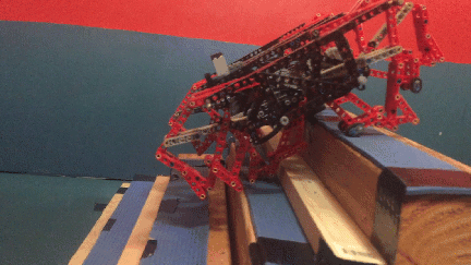
In this test, 10 pounds were added to TrotBot with 3 versions of feet:
1. feet with heel and toe linkages 2. feet with only heel linkage 3. feet without heels or toes. As can be seen in the video, TrotBots without heels and toes should be built in a 12 leg version to handle heavy loads. Also, we added 10 pounds to a toe-less TrotBot that used LEGO's plastic axles, but its bumpier gait required more torque than the plastic axles could handle. Those axles twisted so much that TrotBot could barely walk, so we replaced them with steel axles before filming this test. We should have included a clip of the plastic axle version to better show how heavy walkers with bumpy gaits may need LEGO's plastic axles replaced with steel axles to handle the torque. An alternative to adding heel/toe linkages to TrotBot is to build it in a 12-leg version, which results in a similar increase in foot-contact with the ground. However, it's a wider build, so the longer crank/axle system will twist more if LEGO's plastic axles are used. For this reason we usually replace at least the inner leg's plastic axles with steel axles when building 12-legged walkers.
2 Comments
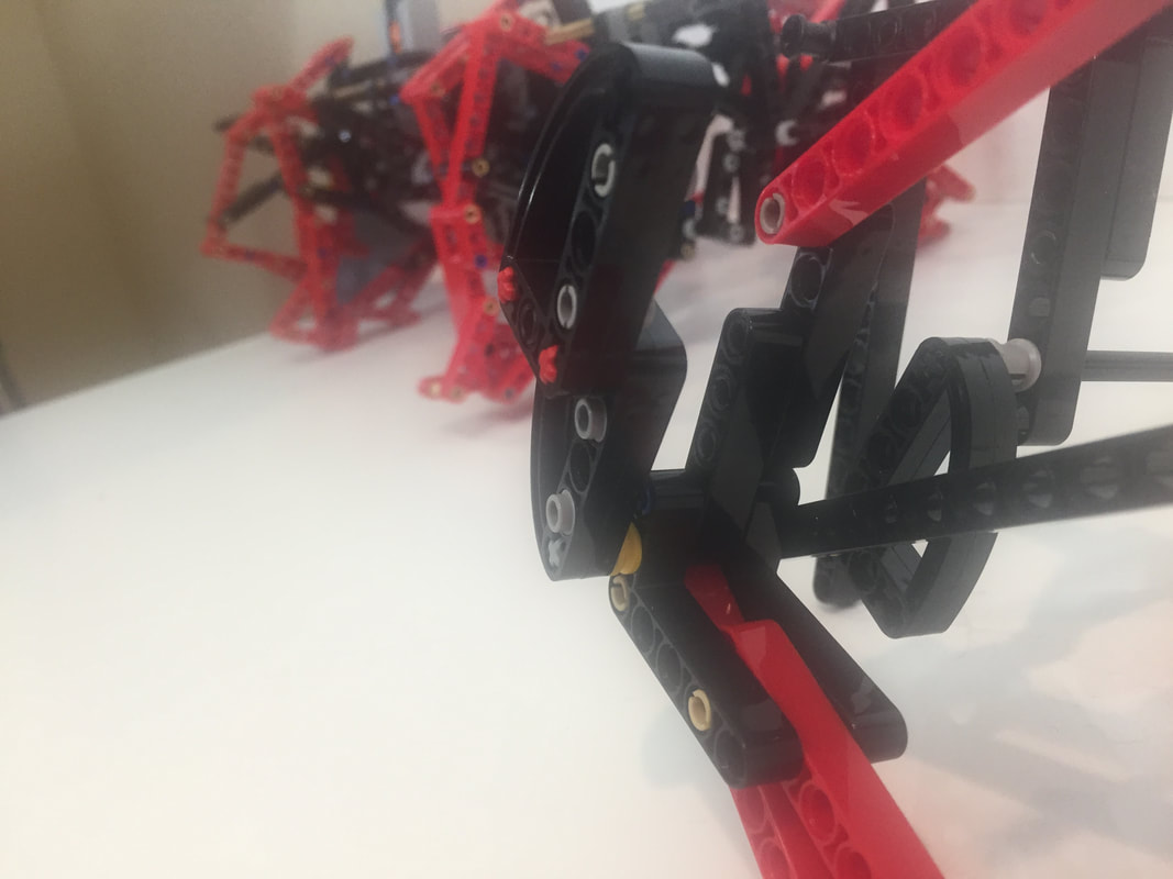
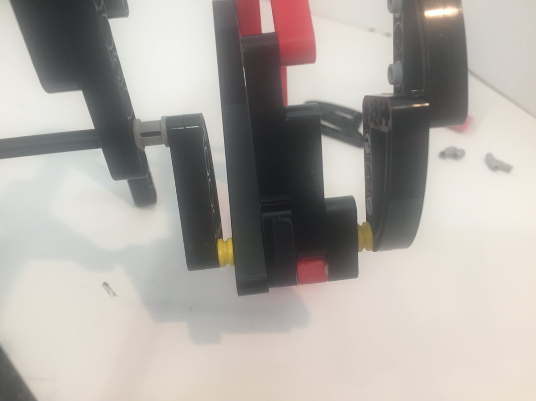
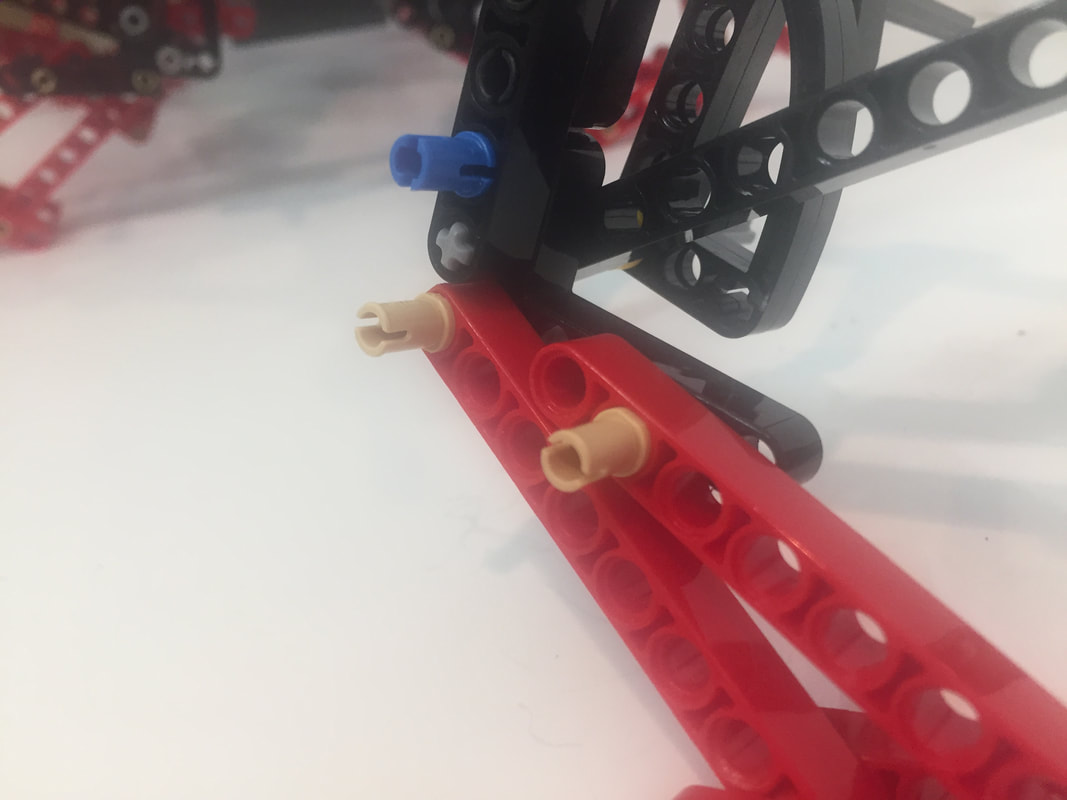
TrotBot's lower leg pins tend to come out when the legs experience sideways forces, as can happen when turning TrotBot on terrain with a lot of friction (like on thick carpeting).
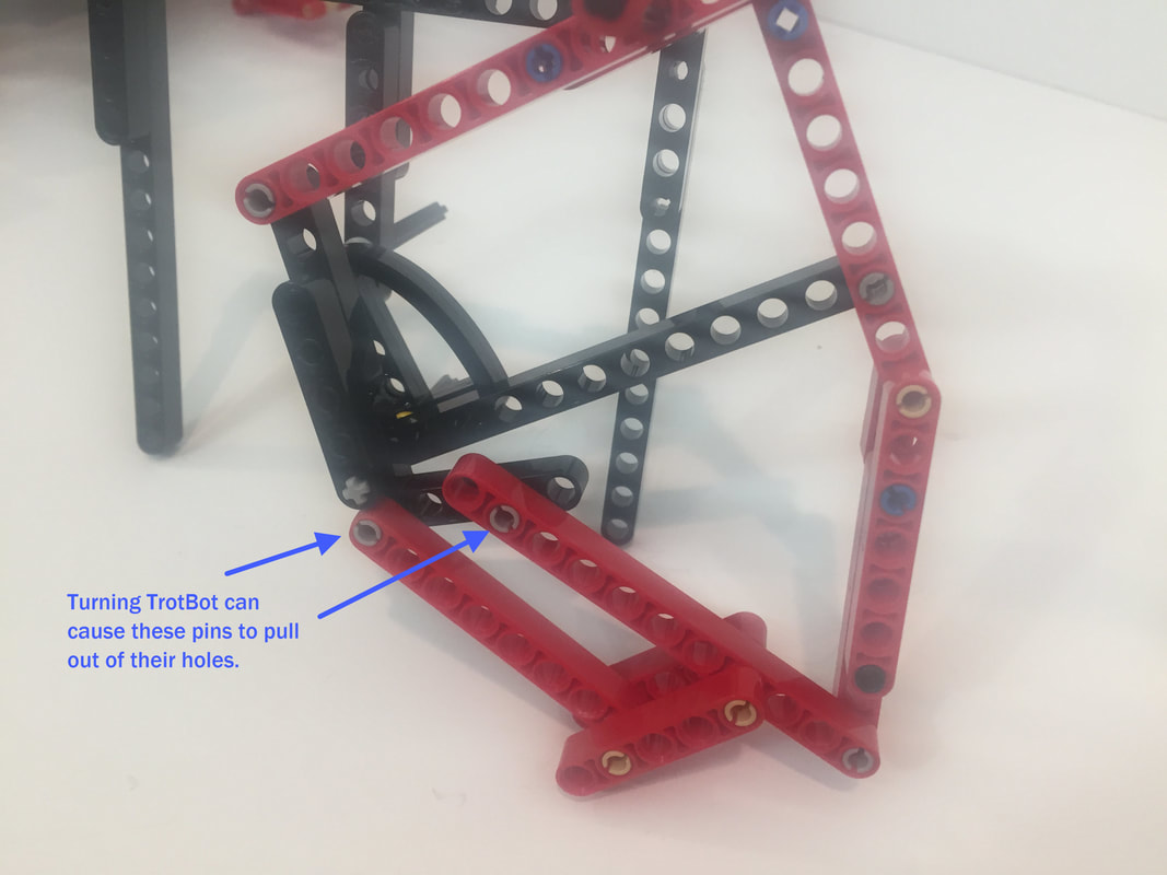
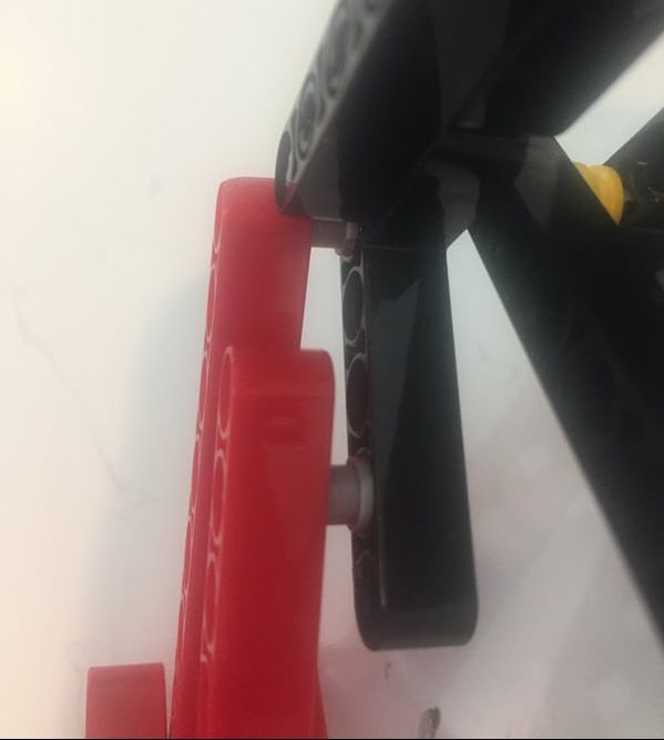
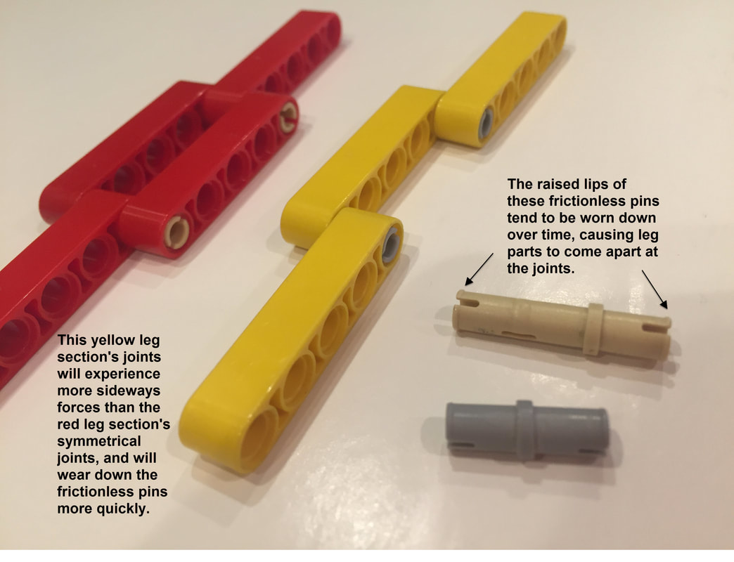
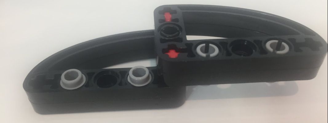
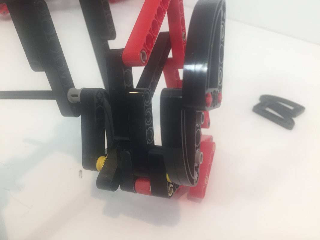
If the legs aren't snapped back in place, then friction on the pin's lips will wear them down, and the pins will no longer join with a sharp "snap", causing them to pull out more easily. Ideally, joints should be 3 beams wide and symmetrical like the red chain of beams below, which prevents pins from pulling out or bending sideways when bearing weight:
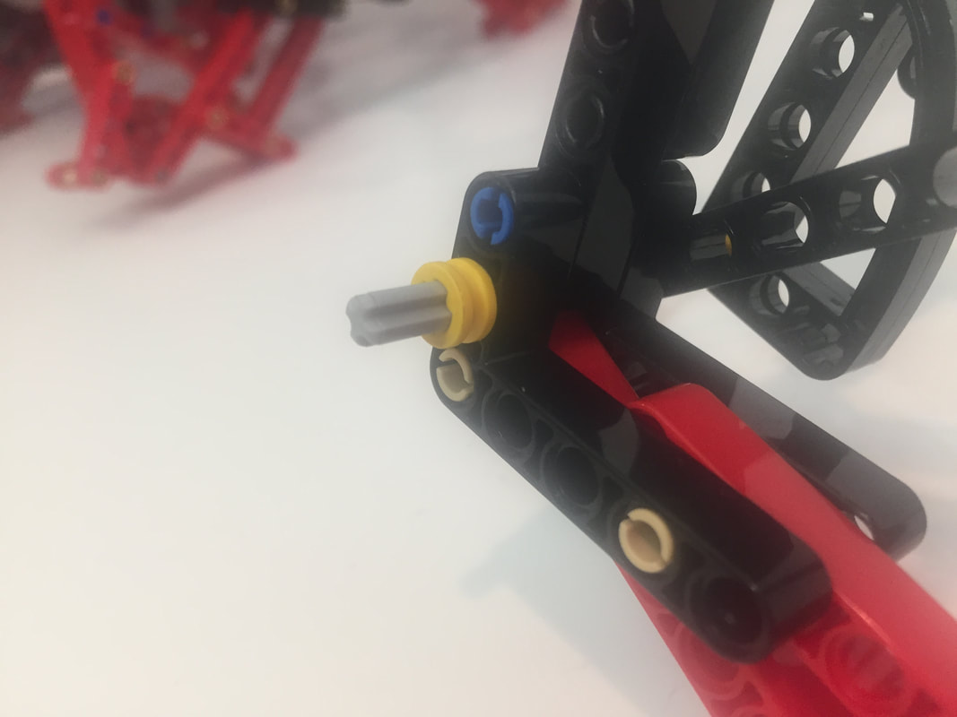
However, using LEGO's parts to sandwich TrotBot's leg joints inline like the red beams above would add a lot of width to the robot. Instead, I sandwiched the leg joints by attaching an additional 3x5 L-shaped beam to the outside of the legs, which is a bit off center but still works well with LEGO's high strength-to-weight ratios. I tested these new attachments by turning TrotBot on some thick carpeting, which would usually cause a few of the leg's pins to pull out. Below the video are some pictures of how I added the parts, and I used these attachments in my TrotBot version 3 builds.
I've got a few other ideas to test over the next few weeks, and then I'll post some new TrotBot instructions with the improvements. UPDATE: Here are the new instructions with a part list.
Recently I’ve been working on getting TrotBot to climb 1/3-scale stairs. The first video below shows TrotBot climbing stairs at the standard 32 degree angle of life-size stairs, both with and without wheelie bars. The second video shows TrotBot attempting steeper 38 degree angle stairs without wheelie bars, and required a bit of expert driving to avoid flipping backwards!
In this process, I found that TrotBot’s center of gravity needed to be lowered to prevent it from flipping backwards, so I lowered the battery box.
In general, vehicles handle better with a lower center of gravity, so I should have mounted the battery box lower in my original instructions. Instructions to modify TrotBot to lower its battery box:
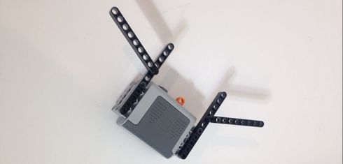
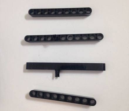
These instructions require the vertically oriented 7 hole beams that mount the battery box to the frame be replaced by 11 hole beams. Using 11 hole beams allows the battery box to be mounted a half dozen holes lower than it would be otherwise.
Start by removing the battery box and vertical 7 hole beams from the TrotBot frame, and get four 11 hole beams to replace the 7 hole beams. NOTE: it's easier to pull the two sides of TrotBot apart incrementally while rotating each metal support rod between pulls so that the LEGO beams can slide along the rods. 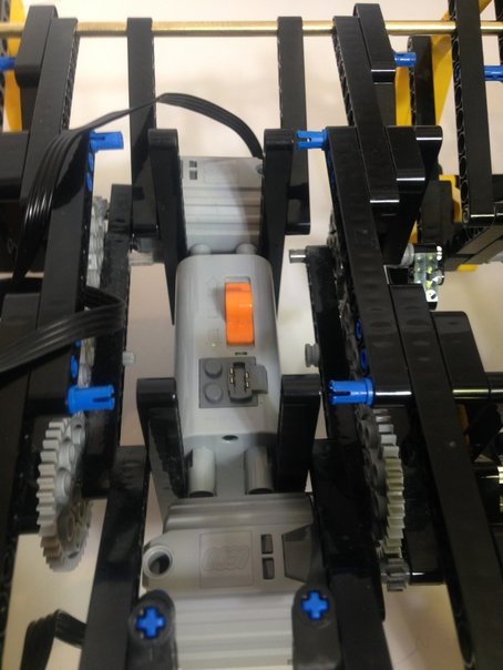
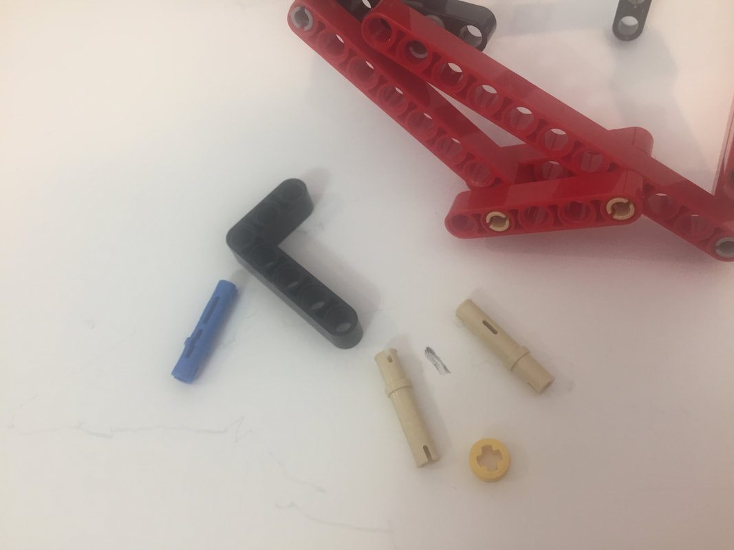
The following photo shows the attachment of two 11 hole beams to the battery box along with the 9 hole beams that attaches to them to the metal support rods to form the hypotenuse of the frame triangle. The 9 hole beams that are used as the hypotenuse will remain on the metal support rods and are only in the pictures to provide context. 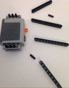
Attach the 11 and 9 hole beams together to form the basis for the frame triangle. The 9 hole beams must be mounted on the 5th hole from the top of the 11 hole beam.
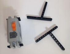
Mount these parts onto the battery box. Notice that the 9 hole beams are mounted on the outside of the 11 hole beams, that they are facing away from the battery box.
Repeat this process for the other side of the battery box.
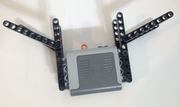
Next mount this structure back into the TrotBot frame.

And that's it, TrotBot with a lowered center of gravity - time to work on TrotBot's next climbing challenge:

|
Categories
All
Archives
February 2023
|
 RSS Feed