|
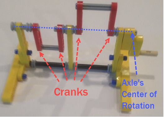
Way back in 2016 we posted some ideas for how to make strong 120 degree cranks in LEGO here. We still get questions about 120 degree cranks, so here is another diagram to show how LEGO's Technic rotor part #44374 could be used to make cranks of length 2 LEGO holes to drive 3 legs 120 degrees out of phase. The purpose here is not to limit you to only using LEGO's rotors when making 120 degree cranks, but instead to use the rotors to illustrate the geometry of a 120 degree crank/axle system - hope it helps to clarify things. Good luck, Wade 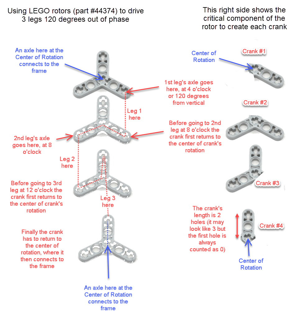 Notice that every crank connection is keyed such that every axle connected to them is forced to rotate along with the crank, which transfers the rotation to the adjacent crank. Note: if you are building larger or heavier walkers you may want to support the axle between each leg with beams that connect the Center of Rotation to the robot's frame, as is done in the simple 180 degree crank/axle system below (of course, instead of using a single beam connection like below you should use two diagonals that connect the Center of Rotation to the front and back sides of the frame, creating a strong triangle that resists front/back forces)
0 Comments
Walking Tanks? Applying Prof. Shigley's Pioneering Study of Mechanical Walkers to Strider's Linkage7/7/2018 
Posted by Wade
If you are looking for ideas on how to create highly functional mechanical walkers, Professor Joseph Shigley's 1960 feasibility study for the army is a great resource. It combines engineering rigor and sound reasoning to illuminate many of the challenges, and potential capabilities of mechanical walkers. 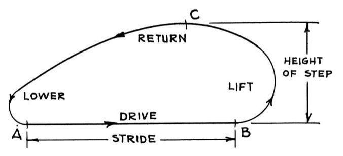
Shigley's Foot-Path Diagram
To meet the requirements of walking tanks, Shigley sought a mechanism that could:
To meet the rugged terrain and speed requirements of tanks, much of Shigley's study focused on the foot-paths of mechanisms. Below is Shigley's diagram of foot-path types, with type E representing his ideal type for rugged terrain and fast speeds. 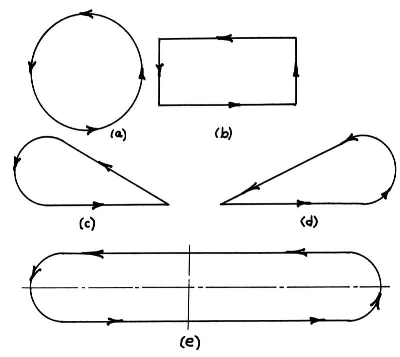
Shigley's foot-path types, with path E representing his ideal type for high functionality
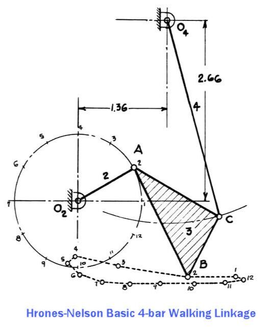
When Creating New Mechanisms, Start By Investigating 4-Bar Linkages In general, the fewer bars in a linkage, the better (lower costs and build-times, less mechanical complication and friction, etc.). So, searching for a mechanical solution based on a 4-bar linkage is usually a wise first step. Shigley advised searching thru Hrones-Nelson's atlas of hundreds of 4-bar linkage coupler curves as a "good first approach to such a problem", which must have been a vital resource for mechanical engineers in the days before personal computers. Below is one of the better 4-bar linkage configurations Professor Shigley found in Hrones-Nelson's atlas, but it doesn't step high enough for rugged terrain.
Shigley described how the step-height could be increased by allowing a joint to slide along a cam groove, but we wanted a mechanism that could be prototyped in LEGO. So, instead we experimented with pairing two 4-bar linkages into a combined 10-bar linkage with front and back legs, such that the rear leg lifted the front foot and vice versa. This allowed us to increase the step-height significantly. 
To increase step-height, Strider's linkage pairs two 4-bar linkages into a combined 10-bar linkage with front and back legs, such that the rear leg lifts the front foot, and vice versa
We found that the boat-shape of Strider's foot-path mitigates this problem, since the foot's horizontal speed during the lift and lower phases is similar to the foot-speed of the drive phase. This can be seen in the above GIF of Strider walking across the screen. Notice how the bottom halves of its lift and lower phases are nearly vertical, which means that when a foot steps on an obstacle halfway down its lower phase it will be less likely to skid or cause the robot's forward motion to stop while stepping up onto the obstacle.
The impact of the boat-shape can be exaggerated by reducing the number of legs from 12 to 8, causing the feet to contact the ground well above the bottom drive phase of a 12 leg Strider: 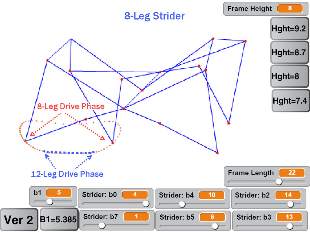
You can see this in action in the below video of an 8-legged Strider walking on rocky terrain, where Strider's feet often contact the rocks well above the bottom drive phase, yet the robot's speed remains fairly consistent as it walks across the rocks: Triangular Foot-Paths How robot speed varies as ground height changes can also be gauged by simulating the front legs while keeping the mechanism horizontal, which results in fairly consistent speed for mechanisms with rounded foot-paths like Striders, and also serves to cushion the impact of hitting obstacles somewhat like a spring-based suspension: 
In contrast, the feet of robots with triangular foot-paths will be going the wrong way when stepping on/off obstacles, or when the terrain's slope changes abruptly. If the feet can't skid, then the change in the terrain's elevation can push the robot backward, as happens to Klann's Mechanical Spider below. If the rear legs aren't stepping on a similar obstacle at the same moment, then they'll be pushing the robot forward as usual, fighting the front legs and potentially jamming the mechanism. 
Robots with triangular foot-paths can get pushed backward when the terrain's elevation changes
Here's a test of how Strider and Klann linkage robots handle elevation changes, using a slope change to make the test scale-independent: Foot-Path Symmetry The front-to-back symmetry of Strider's foot-path results in fairly consistent horizontal speed when the terrain's elevation changes on either side of its foot-path - e.g. when either ascending or descending the stilts in these simulations. In contrast, TrotBot's foot-path is somewhat teardrop-shaped. This causes TrotBot's horizontal speed to drop when encountering large elevation changes on the shorter, inner side of its foot-path, which can be seen in the below simulation when TrotBot steps down to a lower stilt:. 
TrotBot's somewhat teardrop-shaped foot-path causes it to slow down when stepping off of high obstacles
Tank-Scale Functionality on Rugged Terrain? Strider's high-stepping, boat-shaped foot-path allows it to meet Shigley's rugged terrain requirements fairly well at LEGO-scale. However, tank-scale functionality on rugged terrain is another matter, which would require the robot to be strengthened dramatically due to the lower strength-to-weight-ratios of larger scales. Furthermore, increasing strength typically involves adding structure and motor power, which further increases weight, which requires even more structure, which adds even more weight and costs, etc.
The legs in particular would need to be strengthened, since walking along the side of a hill, or turning the walker tank-style while on rugged terrain would put a tremendous amount of sideways forces on the long legs - if it were even feasible at such large scales. However, adding too much structure and weight to fast-moving legs would create other problems. Instead, perhaps the lower half of the legs could be supported laterally by rails connected to the frame? Rails that created channels that the leg's path should follow? Positioned below the legs' knee and "hamstring" joints to reduce sideways forces on these weak points? Eh......for rugged terrain I think I'll stick to smaller-scale walkers, which also benefit from Shigley's insights.
High Speed Walking As Shigley described, an ideal walking mechanism for a tank should have the constant horizontal speed of a wheel, while also being able to step over obstacles that block wheels. Strider has relatively constant foot-speed, as indicated by how little the feet skid in the following video. Since the feet aren't constantly accelerating/de-accelerating the robot this improves the gait's efficiency, and Strider is the only mechanism that we've tested which can walk with a 1:1 gear ratio without the LEGO motors stalling: High Speed Vibration Shigley also described how the vertical and horizontal inertia forces of leg mechanisms should be balanced for a tank to walk fast without vibrating itself to death. Such vibration isn't much of a problem at LEGO-scales, but it gets exponentially worse as scale increases. If you've ever driven a vehicle where the steering wheel shakes due to its wheels being out of balance, and seen how it's corrected by attaching small metal weights to the wheels, then you can probably imagine how much worse the vibration problems could be for a vehicle with large mechanical legs running at high RPMs. 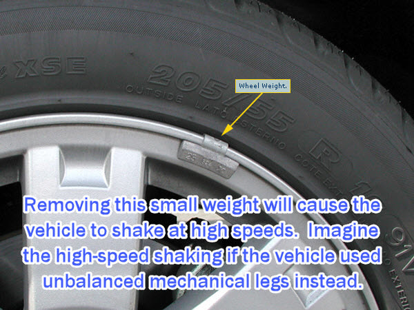
Strider's mechanism would need to be modified in order for a large-scale version to walk at high RPMs with limited vibration. If curious, Shigley's study below shows how to mathematically analyze inertia forces by calculating the horizontal and vertical accelerations of the legs' masses, and gives some suggestions for balancing them.
Load Bearing and the Linkage's Bar Count The more bars a linkage has, the more joints it needs. Each joint adds friction. Furthermore, the joints will always have some play, which can cause long legs with many joints to bend sideways under loads, especially when turning them tank-style. Like Klann's sturdy 6-bar linkage, Strider's linkage has relatively few bars per leg with 10 bars per leg pair, versus TrotBot's and Strandbeest's 8 bars per leg. If implemented well, this implies that Strider's linkage has the potential to be relatively energy efficient and should be able to handle loads relatively well. Below tests linkage variation #6 with a 25 pound load. The plastic parts bend and shift somewhat under the load, increasing the difficulty of carrying the load, but the LEGO motors didn't stall. Also, we were planning on uploading a video with Strider self-destructing at the end by attempting to turn it while carrying 25 pounds. Some of our other walkers self-destructed while carrying much less weight, so we were a bit surprised that Strider survived with its legs intact. Strider's low bar count per leg does appear to result in a stronger linkage.
Notice how adding the weight causes Strider v6 to have a stammering gait, which is partially due to Variation 6 having less consistent foot-speed than does Variation 7 featured in the slow motion video above.
Before performing this test the plastic LEGO axles were replaced with steel axles to handle the torque. Other than that, and the 2 steel support rods, all of the parts are plastic LEGO parts connected by LEGO pins (no glue). Strider's linkage dimensions can be found here, and other configurations of Strider can be found here where you can also create your own customized Strider linkage with an interactive simulator. Below is Prof Shigley's feasibility study, a 1960 Popular Science article discussing it, and the Hrones Nelson Atlas of four bar linkage coupler curves.
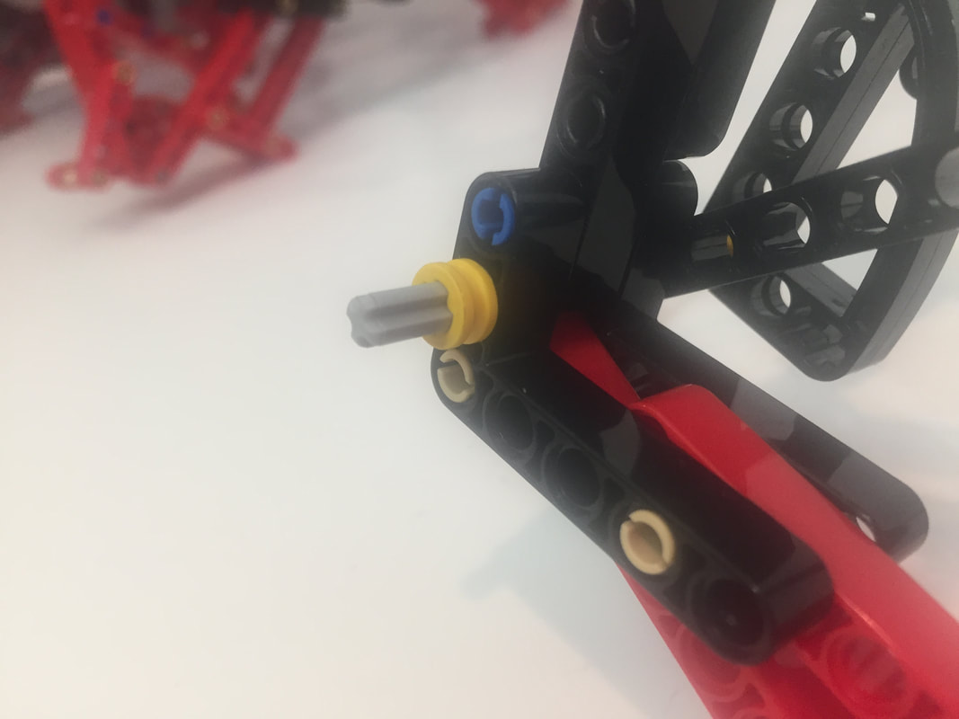
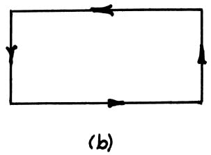
TrotBot's lower leg pins tend to come out when the legs experience sideways forces, as can happen when turning TrotBot on terrain with a lot of friction (like on thick carpeting).
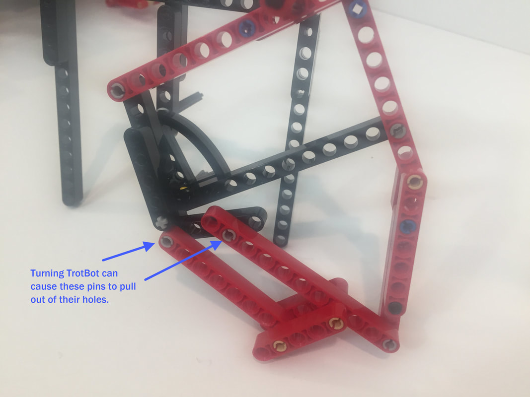
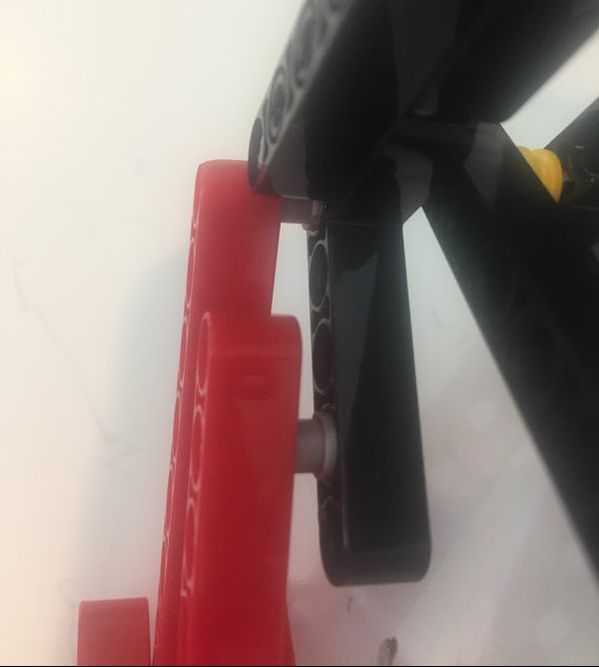
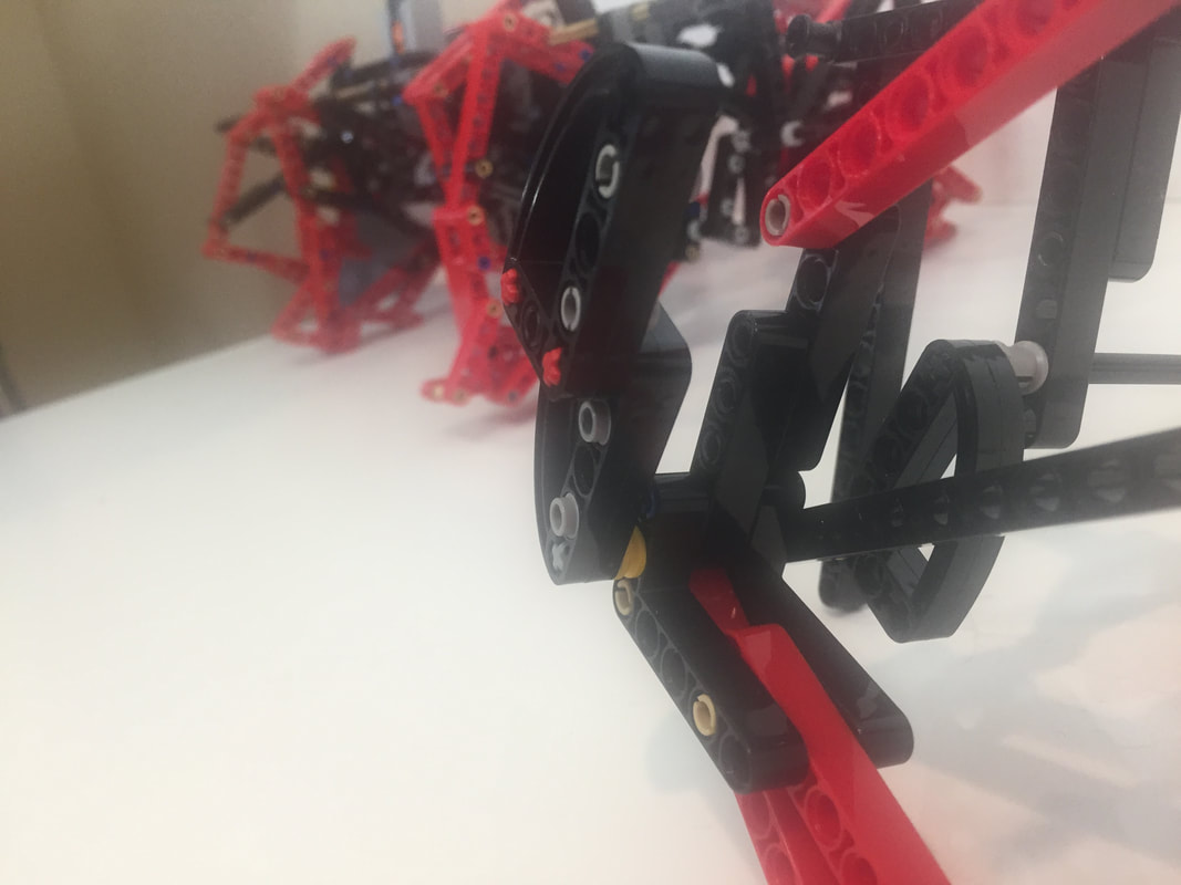
If the legs aren't snapped back in place, then friction on the pin's lips will wear them down, and the pins will no longer join with a sharp "snap", causing them to pull out more easily. Ideally, joints should be 3 beams wide and symmetrical like the red chain of beams below, which prevents pins from pulling out or bending sideways when bearing weight:
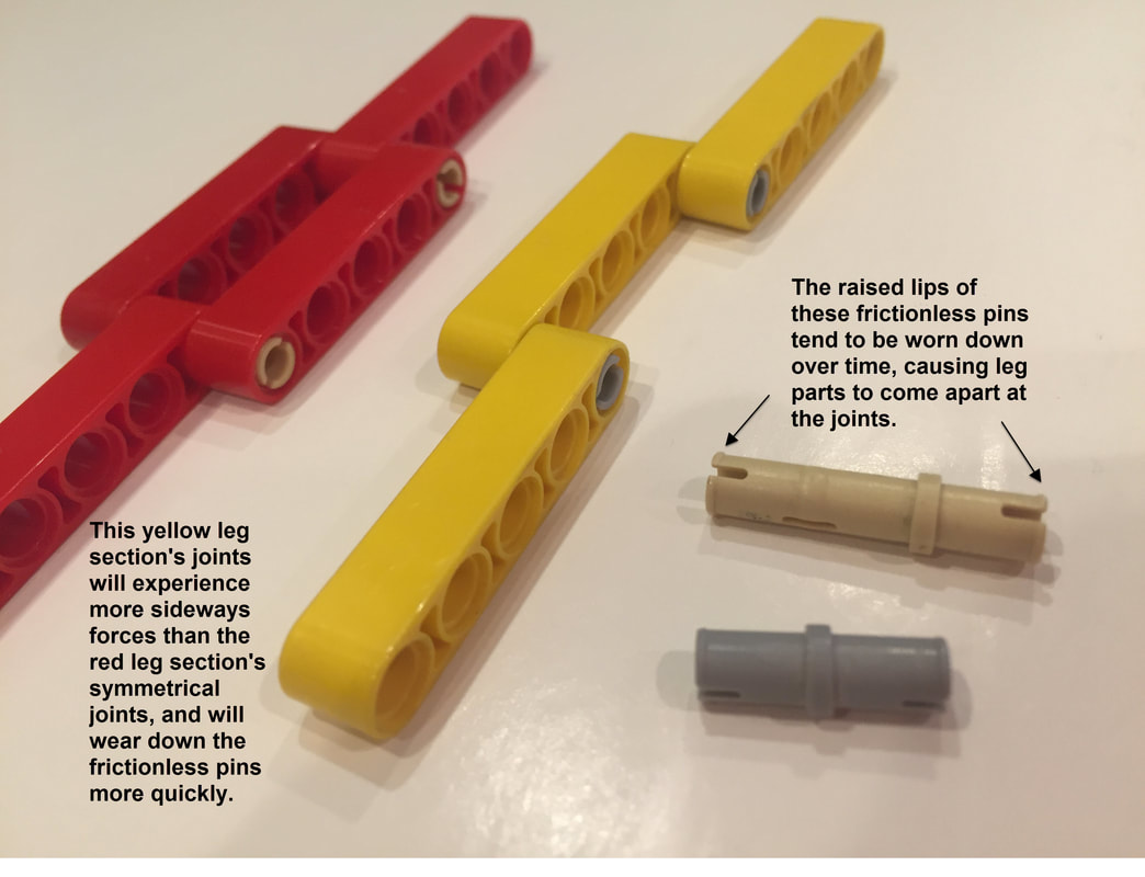
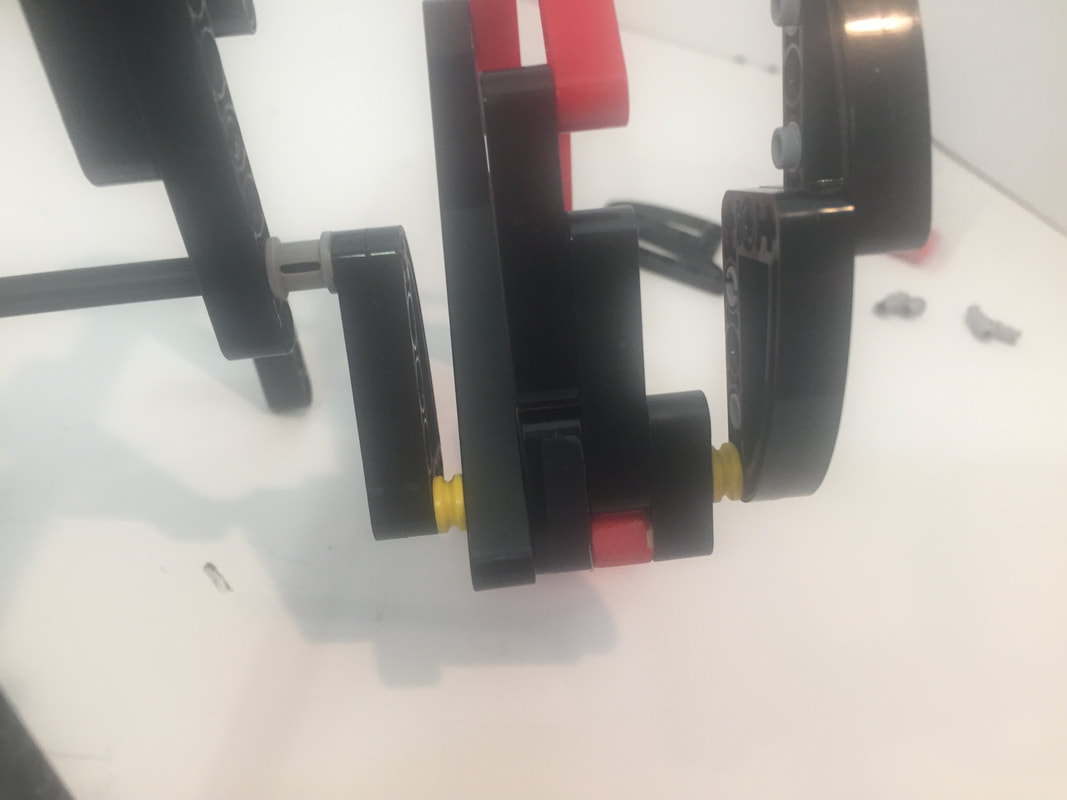
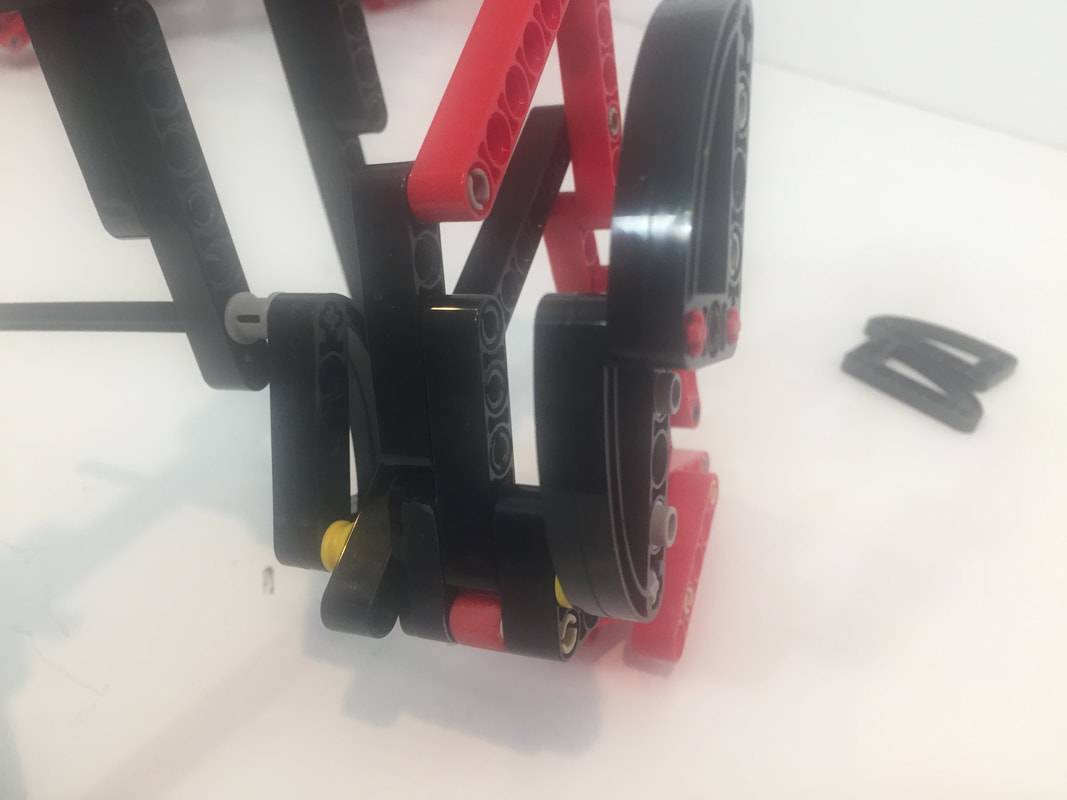
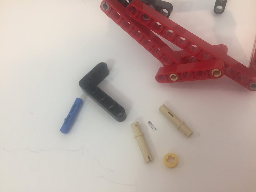
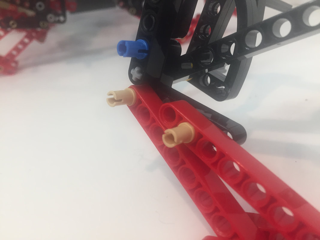
However, using LEGO's parts to sandwich TrotBot's leg joints inline like the red beams above would add a lot of width to the robot. Instead, I sandwiched the leg joints by attaching an additional 3x5 L-shaped beam to the outside of the legs, which is a bit off center but still works well with LEGO's high strength-to-weight ratios. I tested these new attachments by turning TrotBot on some thick carpeting, which would usually cause a few of the leg's pins to pull out. Below the video are some pictures of how I added the parts, and I used these attachments in my TrotBot version 3 builds.

I've got a few other ideas to test over the next few weeks, and then I'll post some new TrotBot instructions with the improvements. UPDATE: Here are the new instructions with a part list.
|
Categories
All
Archives
February 2023
|
||||||||||||||||||

 RSS Feed