|
Posted by Wade
These experiments are a continuation of an earlier post on shock-absorbing feet, where I wasn't able to significantly smooth walker gaits without either:
This variation of shock-absorption via spring-loaded ankles avoids these problems, and is able to smooth Strider's gait while also increasing the percentage of foot-contact per crank rotation, which boosts stability and reduces slightly the need for more legs. 
Strider Ver 3 with Shock-Absorbing Heels
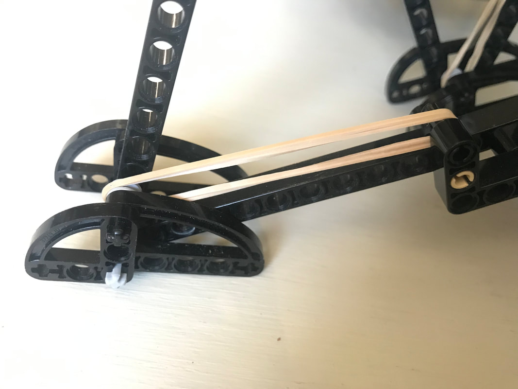
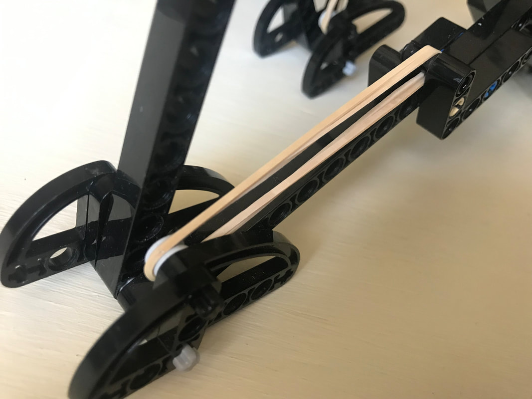
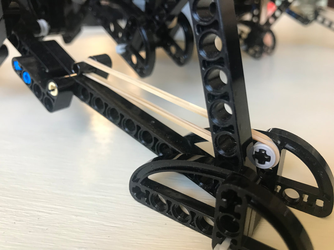
The need for damping is reduced by using a spring which is weak enough to allow the heel to "bottom out" as the robot steps onto the ground, which mitigates bouncing. Yet, as can be seen in the second video below, the heels' springs still absorb much of the shock when the robot steps down to the ground hard and fast even if the heels are compressed completely. Additionally, much of the energy absorbed by compressing the heel and stretching the spring is returned as the foot is lifted off the ground. Furthermore, the arc of the heel's rotation around the ankle joint tends to push the robot forward when the front foot lands, or the rear foot lifts, which helps to compensate for Strider's slightly slower foot-speed at that point in its foot-path. There are a number of ways this idea could be implemented, such as via a compression spring that pushed the heel down, but I opted to use a simple rubber band to pull Strider's toes up, which rotates the foot at the ankle joint and pushes the heel down. 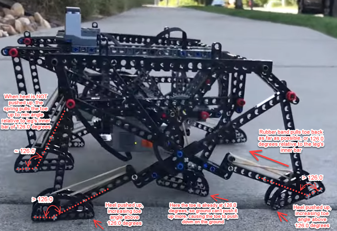
Strider's toes function as usual here, where they push down on the ground on the inner side of the foot-path. The toes are not involved in the heel's spring-based shock absorption - only the heels absorb shocks.
Below are tests of two variations of shock-absorbing heels. The first test uses longer heels like the GIF above: The second test below uses shorter heels, which don't always compress fully and look to be inferior to longer heels....but some load-bearing, top-speed, and high-speed vibration tests should be performed to confirm which heel length is indeed superior. Conclusions? I recommend adding the longer version of shock-absorbing heels to 8 and 12 leg Strider robots, and as their weight increases use stronger rubber bands to handle the weight. However, I do not recommend building huge Striders in 8-leg versions regardless of adding shock-absorbing heels. Strider's high, boat-shaped footpath has a longer perimeter than walkers with triangular foot-paths like Jansen's Strandbeest or Klann's linkages, which reduces Strider's foot-contact with the ground to about 1/3rd of the crank's rotation. Therefore, for large-scale Strider builds use at least 12 legs. Good luck, Wade
2 Comments
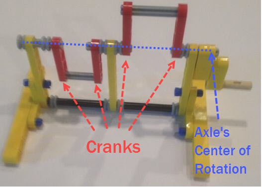
Way back in 2016 we posted some ideas for how to make strong 120 degree cranks in LEGO here. We still get questions about 120 degree cranks, so here is another diagram to show how LEGO's Technic rotor part #44374 could be used to make cranks of length 2 LEGO holes to drive 3 legs 120 degrees out of phase. The purpose here is not to limit you to only using LEGO's rotors when making 120 degree cranks, but instead to use the rotors to illustrate the geometry of a 120 degree crank/axle system - hope it helps to clarify things. Good luck, Wade 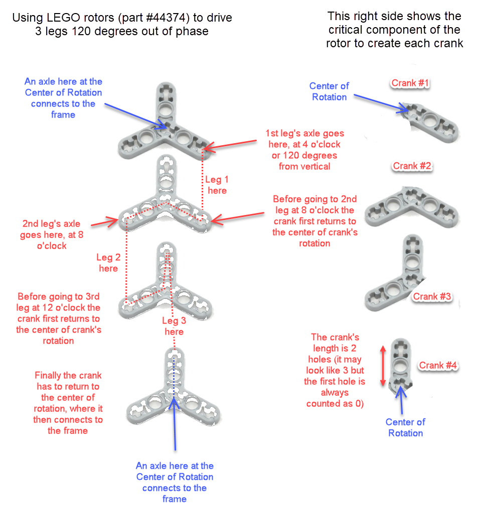 Notice that every crank connection is keyed such that every axle connected to them is forced to rotate along with the crank, which transfers the rotation to the adjacent crank. Note: if you are building larger or heavier walkers you may want to support the axle between each leg with beams that connect the Center of Rotation to the robot's frame, as is done in the simple 180 degree crank/axle system below (of course, instead of using a single beam connection like below you should use two diagonals that connect the Center of Rotation to the front and back sides of the frame, creating a strong triangle that resists front/back forces)
Posted by Oracid (Editors note: you can see more of Oracid's inspiring creations here) My goal is to explain simply how one can go from a usual 5 bars linkage to a 5 bars linkage with extension. The interest of this last mechanism is that it approaches the biological reality of a quadruped or a biped. In Fig.1, I show the equivalence between a usual 5 bars and its diamond-shaped reduction. The difference between these two linkages is located at the g bar which is fixed to the chassis. In the second linkage, the 5 bars turn into diamond with g = 0. Only the axis of rotation remains which fixes the 5 bars to the chassis. 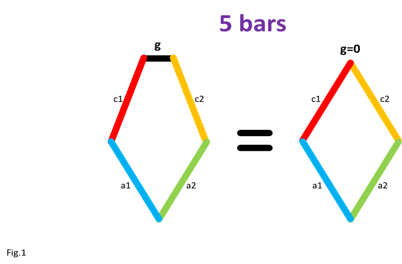
Editor's note: the cranks add additional bars to the 5 bars shown here
In Fig.2, I show that the shape of the bar c1 does not matter, provided that its ends keep the same position. For clarity, only the left side of the 5 bars is shown. 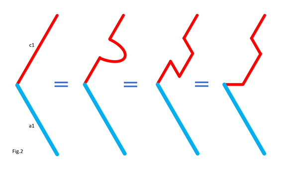
In Fig.3, I show that we can move part of the line c1, provided that the parts are connected by an articulated bar forming part of a parallelogram. For clarity, only the left side of the 5 bars is shown. Here is how to go from the assembly in Fig.3-1 to the assembly in Fig.3-2 by translating part of the line c1 and the line a1. Notice that point P remains at the same position. 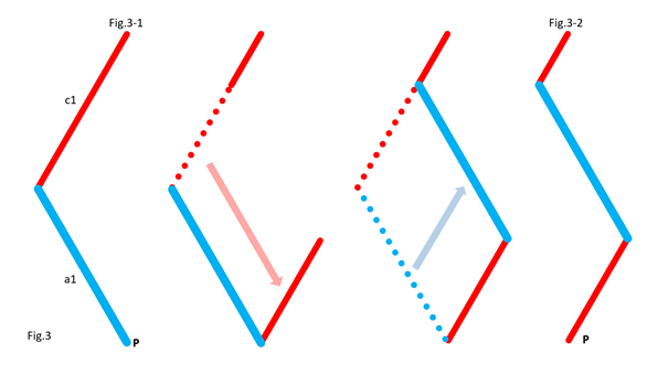
In Fig.4, I show that whatever the angle of c1 with the horizontal in Fig.4-1 and Fig.4-3, there is respectively equivalence of the position of point P in Fig.4-2 and Fig.4-4. It is as if the two parts of c1 are one. This is because a1 and c2 (not shown, here) form a parallelogram which keeps the two parts of c1 at the same angle. For clarity, only the left side of the 5 bars is shown. 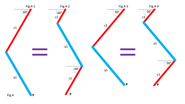
In Fig.5, we can see a summary of the translations of the bars c1 and a1. The bar a1 is positioned at the end of the remaining part of the bar c1, while the “ghost” of the second part of c1 is translated and merged with a2. 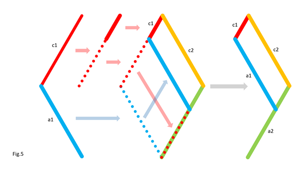
Fig.6 shows the result of the transformation and the equivalence of the two mechanisms. 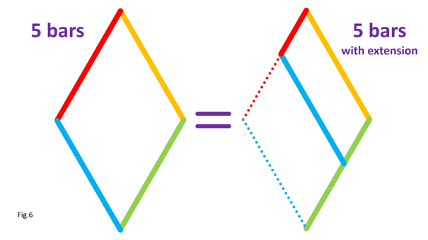
Also, check out Oracid's single DOF linkages, like this: |
Categories
All
Archives
February 2023
|

 RSS Feed