|
Posted by Wade
As we learned during our attempt to scale up TrotBot, not all robot's legs will walk by pushing or pulling the robot. When we pushed TrotBot Ver 0 with its more rectangular-shaped footpath, the cranks would initially rotate, and then the linkage would freeze and the feet would skid on the pavement. Instead, we had to manually rotate TrotBot's cranks to make it walk: 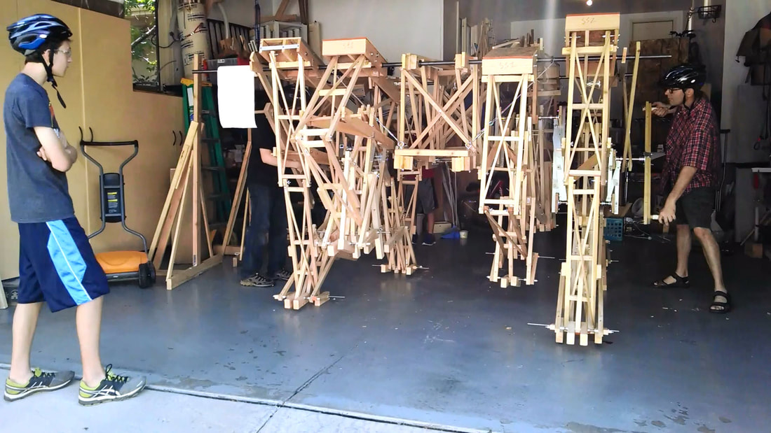
Manually Rotating TrotBot Ver 0's Cranks
The same thing happened when we tried to push our LEGO Klann walkers with the motors disengaged - the feet would skid and the cranks would not rotate. In both cases, this was due to the linkage being at a sort of reverse Dead-Point.
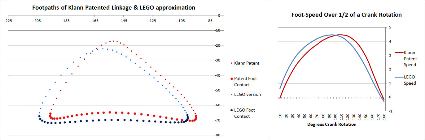
This behavior can be predicted from the image of Klann's linkage below. Notice that when the crank is in such a horizontal position, all four feet are at the bottom corners of Klann's triangular foot-path. Also notice that the feet slow to a virtual stop at these corners, as indicated by how bunched together the red dots are at the bottom corners of the foot-path. In other words, rotating the crank +/- 10 degrees from this horizontal position would barely cause the feet to move. This also means that pushing the robot (and hence the feet) would not cause the feet to move nor the crank to rotate. Instead, it would only cause the legs to bend and the feet to skid, as happens with our prototypes. 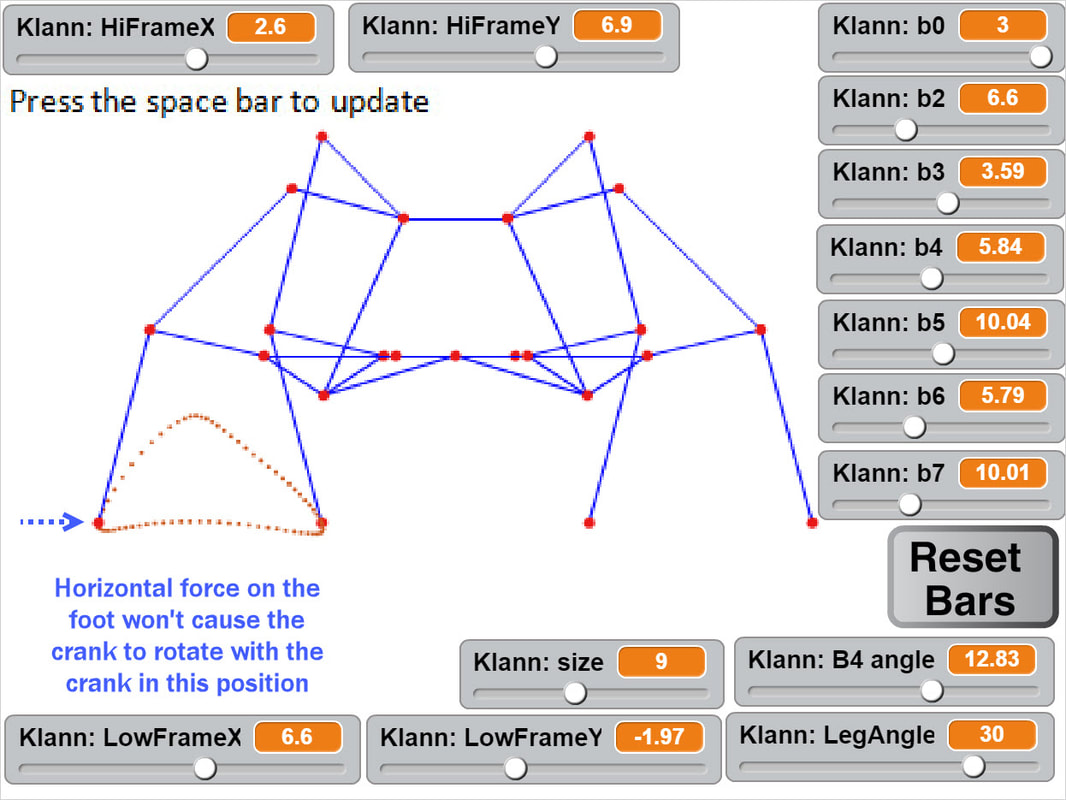
This behavior is also indicated by linked bars being parallel - notice in the image above that the legs' connections to the crank are parallel with the crank, a tell-tale sign of a Dead-Point.
Below the crank has been rotated past this dead point where crank rotation causes foot movement and vice versa: 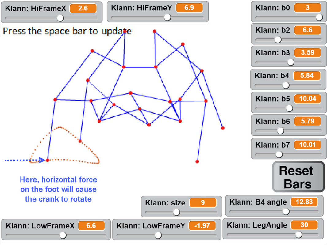
If another pair of legs were added to each side of Klann, as done in the simulation of Strider below, then maybe its legs could be driven by pushing the robot (although one of Klann's feet would still skid at the corner of the foot-path, so it may not work so well - maybe adding feet that could slide or rotate a little would help?) 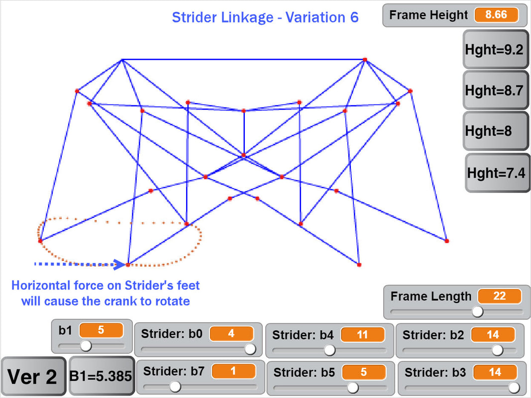
Here's a test to see how easily this linkage variation #6 of Strider's mechanism can be driven by an external force - gravity in this case:
Notice how the robot wavers slightly to the left and right as it descends, due to the foot-speed varying a little. Linkage variation 7 below has more consistent foot speed, and waivers less
Strider Ver 7 Walking Passively
Passive walking can also be tested by pulling the robot with a rope: Strider's legs can also be driven by pushing the robot when built in an 8-leg version, although not nearly as efficiently as 12-leg versions, and the ramp's slope had to be increased to get an 8-legged Strider to walk below: 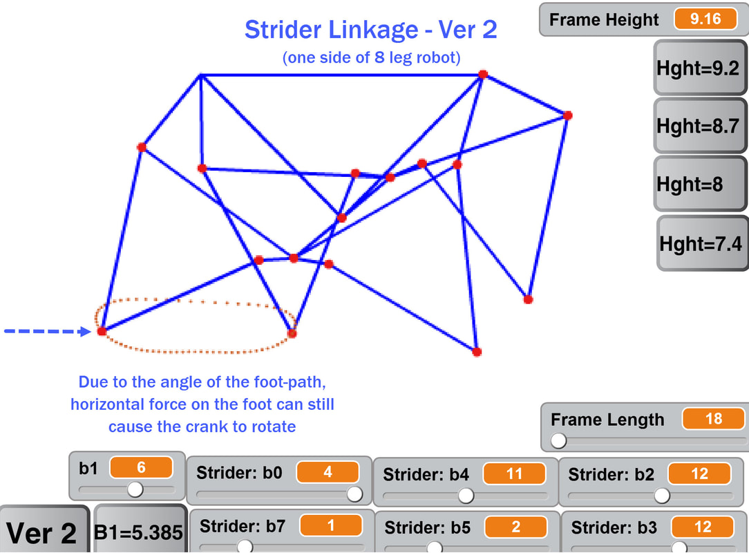
8-Legged Strider Ver 2 Walking Passively with a Bumpy Gait
0 Comments
Posted by Wade
Like how we appreciate Nike's when running on concrete, large-scale walkers benefit from shock-absorbing feet. By increasing the spring's travel, shock-absorbing feet may also be able to smooth the gaits of high-stepping walkers like TrotBot and Strider. And of course this would create new problems to be solved! First, here's the Mondo Spider's feet in action, which provide some shock absorption, and they also slide on the smooth concrete, which helps with turning and with smoothing Klann's speed:
It walks amazingly fluidly considering how Klann's foot-path comes to a stop at each end, and the springs probably smooth the transition between feet somewhat:
Watching the video raises some questions, like:
Implementing Klann's linkage without shock-absorbing feet that slide results in a more halting gait, as can be seen in this version of the Walking Beast: Our LEGO Klann walkers could also benefit from shock-absorbing feet when walking on hard surfaces like wood floors: Next, here are some shock-absorbing feet ideas from Mechanical Walker pioneer, Professor Joseph Shigley: 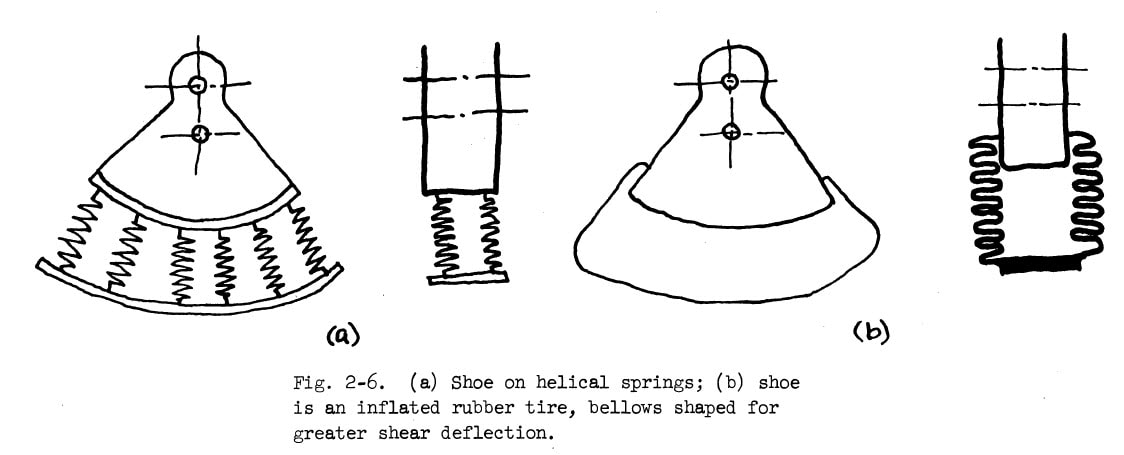
Feet with such springs extend the feet toward the ground. So, in addition to absorbing shocks, the springs also increase the percentage of ground contact of each leg per crank rotation. Taken to an extreme, feet with very long springs could theoretically increase an 8-legged Strider's ground-contact to the point that it always had one foot on the ground at each corner of robot, and do so without causing the robot's height to drop when the feet touching the ground switch. This is because both of the feet will be near the ground at the foot transition, meaning two springs will be pushing the robot up, reducing how far the robot falls at foot transitions. 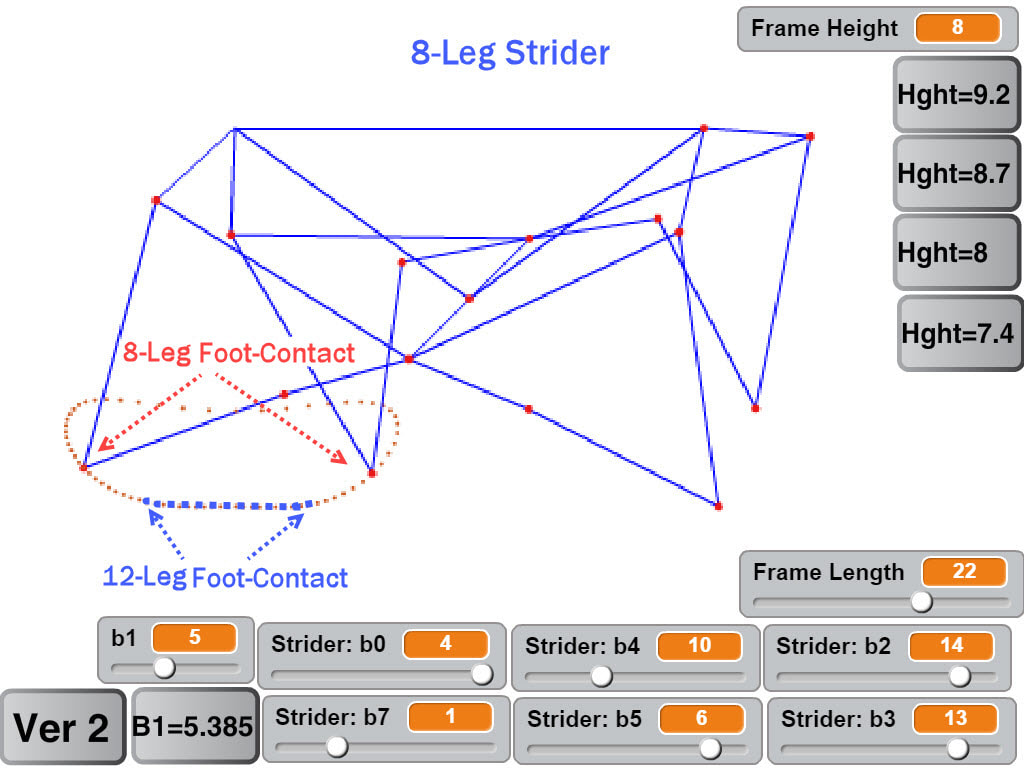
However, a few of the (probably numerous) issues of long-spring feet are:
Like how post-holing in deep snow is exhausting, robots with damped, shock-absorbing feet require more power to walk


Imagine how much more violent this Klann robot's shaking could be if it had long, un-damped springs for feet
So, springs long enough to convert a large-scale Strider to an 8-legged walker wouldn't be feasible, but shock-absorbing feet can still help to reduce the force of impacts of feet with the ground. To illustrate, below are simulations of adding shock-absorbing feet to 12-leg versions of TrotBot and Strider (assuming perfectly elastic springs without damping that comply with Hook's Law, and ignoring inertia and spring oscillation): Notice how adding springs to TrotBot's feet causes the rear feet to skid slightly as its feet are lifted off the ground (because its foot-speed slows at that point in its foot-path). Strider's linkage simulated below has more consistent foot-speed, so its rear feet do not skid when springs are added As an alternative to springs, foam padding can be added to the feet which also provide some damping. This idea is tested below which explores how much an 8-legged Strider's gait can be smoothed by adding thick foam pads to its feet: Below tests foam "boots" on snow and ice: And thinner, foam weather stripping for doors was used in this feasibility test of a jumping robot: On a related note, our LEGO walkers' gaits are somewhat smoothed by the flexing of the metal support rods, although such shock-absorption isn't consistent since it varies depending on how far the legs are from the inner frame. You can see this in action in the following video, where the outer frames bounce more than the center frame:
Posted by Ben
Boris Ingram has been creating some remarkable walkers! Inspired by Theo Jansen’s Strandbeest, Ingram set out to create his own highly functional versions in the early 2000’s. His initial attempt is shown below and was constructed out of plastic straws due to their inexpensiveness and excellent performance under tension and compression forces. 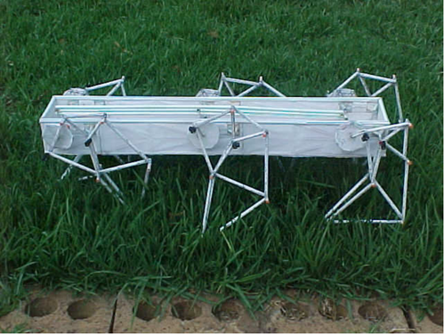
However, like us, Ingram wanted to go bigger. To that end he wrote some linkage simulation software that would allow him to optimize the Strandbeest linkage for:
With this new linkage configuration Ingram was able to construct the absolutely insane 6-legged machine below:
After completing this machine and getting a PhD in mechanical engineering, Boris took a 7 year hiatus from building. During that time he began to brainstorm ways to improve upon his already impressive work.
Boris’ latest design is an octopedal walker. He chose to move from 6 to 8 legs because with only 6 legs there were times where an individual leg was taking a disproportionately large amount of the weight of the machine, somewhat compromising its structural stability. The octopedal machine has the following features: 1. Steerable with variable stride lengths. This allows the legs on the inside of a turn to have a shorter stride length and cover less horizontal distance with each crank rotation. This is important because the outer legs need to travel faster to keep up with the inner legs, as you can see in this classic video on how differentials work:
2. Feet with auto reset in case they meet obstacles during foot placement, a key feature for going over complex kinds of rough terrain.
3. A newly optimized set of linkage dimensions which produce a foot-path that is almost totally flat during the walking phase. This allows the machine to walk more smoothly which in turn reduces the force loads on the legs. 4. Non-constant rotational speed on crank which eliminates deviations in longitudinal velocity (foot-speed). 5. Welded steel construction and ball bearings for low friction. The machine weighs in at about 500 kg with a Kawasaki 200ccc motorbike engine. 6. An additional reduction box incorporating reverse gear and ability to drive inner or outer legs for tank like steering 7. And the ability to ride it! The CAD model of it can be seen below: 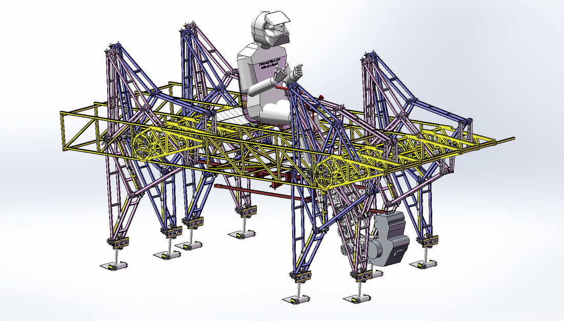
While Boris has done the lion's share of the work, he could use some help from aspiring engineering interns!
If anyone has any interest in helping Boris in the construction of this machine you can contact him at: [email protected] |
Categories
All
Archives
February 2023
|
 RSS Feed